Z force – Cub Cadet Z-Force Series User Manual
Page 19
Z Force
15
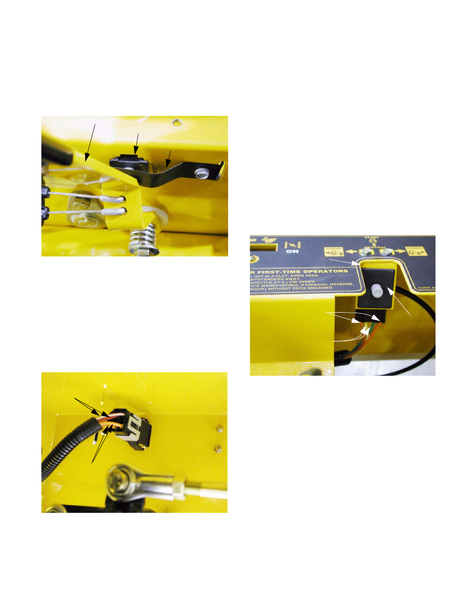
10.2. The Parking Brake Switch is located on the right
side of the control housing. It is accessible by
removing the right side control console. The
switch is actuated by a retainer spring that
moves with the parking brake lever.
See Figure 10.2.
10.3. The parking brake lever must be moved out of
the way, and retainer spring removed to provide
clearance for removal of the parking brake
switch.
10.4. Inside the control housing, the squeeze the tabs
to remove the switch. The harness connector
may be separated either before or after the park-
ing brake switch is removed from the control
housing. See Figure 10.4.
10.5. There are two sets of contacts in the parking
brake switch. Both sets are normally open
(N.O.).
Figure 10.2
Parking brake lever
Parking brake switch
Retainer spring
Figure 10.4
Starter inhibit
circuit
Power to relay #1
Red wires
Orange wires
•
One set of contacts (orange wire and orange
wire with white trace) prevents the starter motor
from turning unless the parking brake has been
set.
•
The second set of contacts (red wire and red
wire with white trace) provide power to relay #1.
When relay #1 is energized, a potential ground
path is created to the magneto, through the neu-
tral switches that are activated by each lap bar.
If relay #1 is energized (parking brake set) and
the lap bars are moved from the start position
notch, the ground path is completed, turning-off
the engine.
10.6. The two park (neutral) switches are located in
the control console on each side of the Z-Force.
Each is actuated by the movement of a lap bar
into or out of the start position notch.
See Figure 10.6.
Figure 10.6
Park
switch
Start position notch
Orange wires
(starter inhibit circuit)
Yellow and green wires
(magneto ground circuit)