Z force – Cub Cadet Z-Force Series User Manual
Page 11
Z Force
7
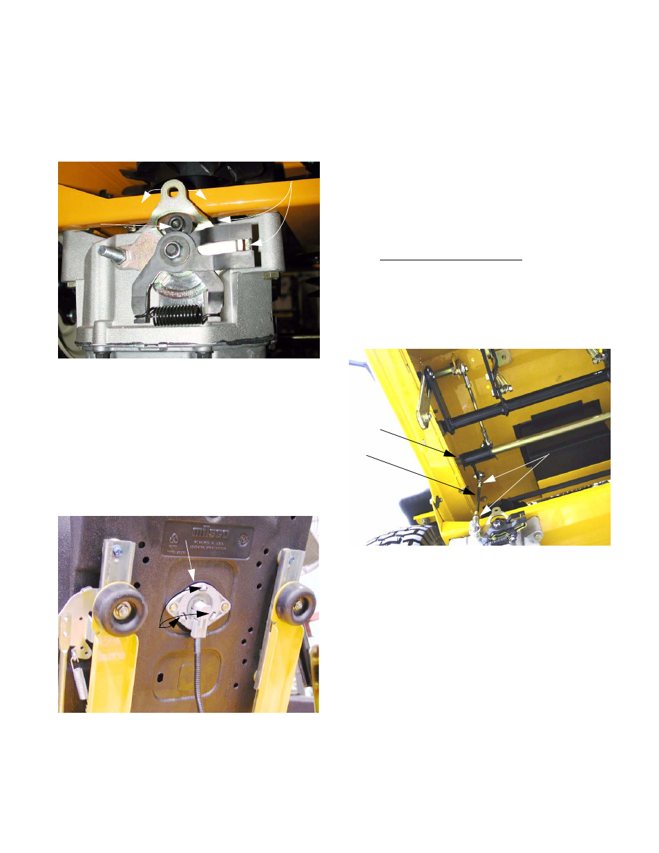
6.16. To adjust the return-to-neutral mechanism,
loosen the socket head cap screw that locks the
indexing plate on the return-to-neutral mecha-
nism in position using a 1/4” allen wrench. It
should be possible to move the indexing plate
with light effort. See Figure 6.16.
6.17. Temporarily disable the seat safety switch.
Because the plug has a double-safety, simply
unplugging the switch has no effect. Applying
pressure to the part of the seat normally occu-
pied by the operator’s gluteus maximus will
extend the three tabs. Clamping one of those
tabs with a pair of alligator clips or a similar tool
will hold the switch in the actuated position.
See Figure 6.17.
6.18. Insure that no unsafe conditions will be created
by starting the engine and operating the drive
system.
Figure 6.16
Indexing plate
Rotate entire mechanism to adjust
cap screw
Socket head
Figure 6.17
Seat safety switch
tabs
6.19. Start the engine. Carefully rotate the return-to-
neutral mechanism until a position is found that
results in no “creep”.
6.20. Tighten socket head cap screw. Confirm that the
adjustment did not shift as the screw was tight-
ened.
6.21. Repeat the procedure on the second IHT, if nec-
essary
6.22. Turn the engine off, and remove the key from the
key switch.
6.23. Reattach steering link rod.
6.24. Enable the seat safety switch.
6.25. The steering link rods can be lengthened or
shortened to adjust tracking.
6.26. Loosen the jam nuts on the link that connects
the bellcrank to the return-to-neutral mechanism.
See Figure 6.27.
NOTE: One end of the steering link rod has a
right hand thread, the other end has a left hand
thread. When both jam nuts are loose, the steer-
ing link rod can be rotated to make a length
adjustment.
NOTE: When adjusting the steering link rods,
maintain sufficient engaged thread length within
the rod end.
Figure 6.26
Bellcrank
Link
Jam nuts