Cub Cadet RZT 22 User Manual
Page 25
21
15.3. The NEUTRAL SWITCHES are in the console
on each side of the unit. They are normally open/
normally closed switches. See Figure 15.3.
-The two inner terminals are N.C. They have a yellow/
white wire which supply a ground to center set of
spades on the PTO switch and spade 87 on the brake
relay.
-The two outer terminals are N.O. The left switch has a
yellow/white wire which goes to the key switch and a
orange that goes to the right neutral switch. The right
neutral switch has the orange wire and a orange/black
wire which leads to the PTO switch.
NOTE: These switches are part of the starting
circuit.
Figure 15.3
Neutral switch
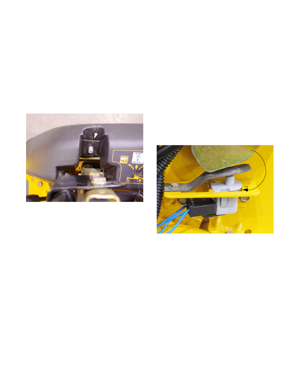
15.4. The REVERSE SWITCHES are located just
under the lapbars in the console.
See Figure 15.4.
-There are two of these switches.
-These are normally closed switches (N.C.).
-The switches need to be set-up in a way that when the
lapbar(s) are pulled to the rear the switch opens the cir-
cuit and eliminates power to the PTO from that switch.
-One lapbar can be pulled back at a time but, if both
are pulled back that will cut power to the PTO. Return-
ing one or both lapbars to neural will reengage the
PTO. This is done by wiring the switches in parallel
-If the reverse safety switch adjustment is not correct,
loosen the reverse safety switch bracket using a 3/8”
wrench. Pivot the bracket and switch to a position that
results in correct operation, then tighten the bracket.
NOTE: It is not necessary to remove either con-
trol console to reach the reverse safety switches,
but it may be necessary to temporarily discon-
nect the blue wires in order to reach the mount-
ing screws for the brackets.
Figure 15.4
Reverse safety switch