Electrical system components – Cub Cadet RZT 22 User Manual
Page 24
20
15.
ELECTRICAL SYSTEM COMPONENTS
This section is intended to help technicians identify the
location and function of specific components on the
RZT electrical system.
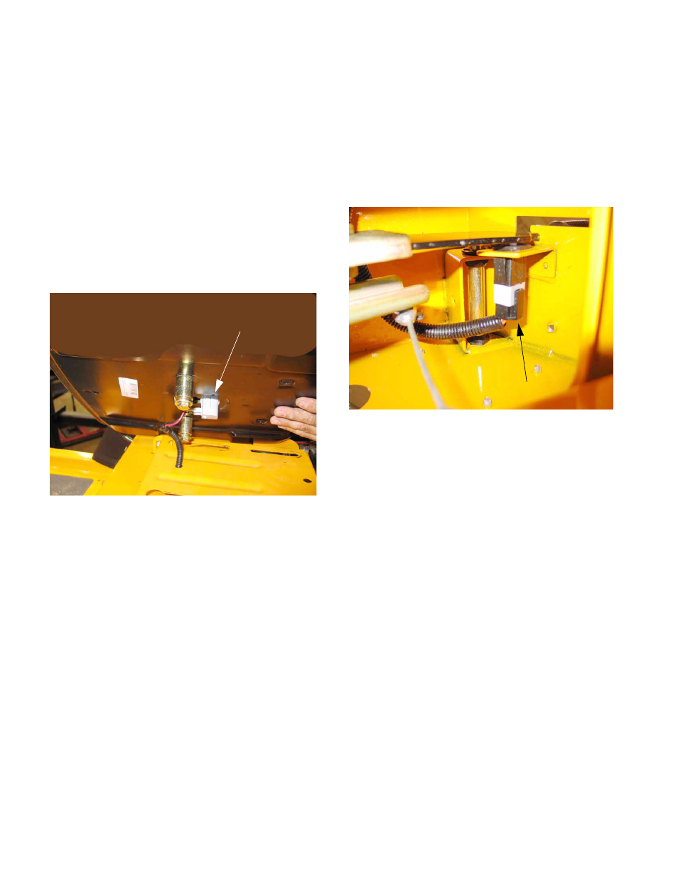
15.1. The SEAT SAFETY SWITCH is located under
the seat assembly. See Figure 15.1.
-The contacts on the switch are normally closed. This
is indicated with the initials N.C.on the side of the
spades.
-When the seat is unoccupied this will energize relay #
1 & 2.
NOTE: The seat safety switch has nothing to do
with the starting circuit.
15.2. The PARKING BRAKE SWITCH is located
under the seat box frame. See Figure 15.2.
-Both sets of contacts are normally open (N.O.).
-When the switch is activated the red wire supplies
power to the seat switch. The red/white wire is for an
indicator light on the hour meter. An orange wire goes
to the starter solenoid. The orange/white wire goes to
the PTO switch.
NOTE: The brake switch is part of the start cur-
cuit.
Figure 15.1
Seat safety switch
Figure 15.2
Brake switch
- G1332 (20 pages)
- i1046 (36 pages)
- i1046 (32 pages)
- 54M (28 pages)
- 980 (20 pages)
- 949 (20 pages)
- Time Save (28 pages)
- 990 (24 pages)
- 997 (36 pages)
- V469 (20 pages)
- 4 Fabricated Deck (32 pages)
- 6 Fabricated Deck (36 pages)
- M48-M60-KW (28 pages)
- 4 Fabricated Deck (36 pages)
- 4 Fabricated Deck (32 pages)
- 6 Fabricated Deck (28 pages)
- 4 Fabricated Deck (32 pages)
- 6 Fabricated Deck (32 pages)
- 4 Fabricated Deck (32 pages)
- CC 500 BAT (30 pages)
- CC 22 (20 pages)
- CC 949 (13 pages)
- 33" Wide Area (29 pages)
- Z-Wing (88 pages)
- TANK S Series: Electrical System (9 pages)
- TANK S Series: Hydraulic Drive & Steering System (12 pages)
- TANK S Series: Steering System Adjustments (11 pages)
- 640 (24 pages)
- 640 (20 pages)
- 641 (20 pages)
- 641 (24 pages)
- J466 (32 pages)
- Series C460 (28 pages)
- 435A (24 pages)
- 642 (24 pages)
- 414 (24 pages)
- M465 (28 pages)
- Fun Runner (117 pages)
- 4 x 2 Big Country - Steel Bed (38 pages)
- 4 x 2 Big Country - Poly Bed & Steel Bed (82 pages)
- 4 x 4 Volunteer (328 pages)
- 6 x 4 Big Country (121 pages)
- CC 4BP 32cc (29 pages)
- 2518-48 (60 pages)
- 1527 (36 pages)