Transaxle replacement: hydrostatic gt – Cub Cadet SLT1500 Series User Manual
Page 68
Series 1000 and 1500
64
•
Install the screw O-rings.
•
Install the lower cover without sealant, to align
the cover and manifold.
Secure it with the 11 perimeter screws.
•
Remove the lower cover, and apply sealant to
the mating surfaces where the cover meets the
transaxle housing.
•
Install the lower cover, tightening the screws to a
torque of 135 to 185 in-lbs.
•
Position a new O-ring seal in the charge pump
housing, and place the gerotor in the housing. If
one edge of the outside of the gerotor is slightly
rounded, it goes into the housing first. The flat
edge rides against the lower cover.
•
Position the charge pump, rotating as necessary
to align the gerotor pump with its drive shaft and
to align the charge pump housing index marks.
•
Install the two socket head cap screws that
secure the charge pump, and tighten them to a
torque of 87 to 108 in-lbs.
33.19. Allow the bottom cover sealant to cure according
to the sealant manufacturer’s instructions, then
fill the transaxle with fluid.
33.20. Any time the transaxle fluid has been refilled, it
will be necessary to purge the air from the
pumps. Air in the drive system will cause:
•
Noisy operation
•
Lack or loss of power
•
High operating temperatures
33.21. To purge the air from the hydraulic system in the
transaxle:
•
Open the relief valve.
•
Start the engine.
•
Slowly cycle the drive pedal from full speed for-
ward to full speed reverse 5 or 6 times, taking
about 10 seconds to complete a single cycle.
•
Stop the engine and check the fluid level at the
fluid level port near the back of the right side
axle housing. The plug can be removed with a 1/
4” Allen wrench. Top-up as necessary.
•
Close the relief valve.
•
Start the engine.
•
Slowly cycle the drive pedal from full speed for-
ward to full speed reverse 5 or 6 times, taking
about 10 seconds to complete a single cycle.
•
Stop the engine and check the fluid level at the
fluid level port near the back of the right side
axle housing. The plug can be removed with a 1/
4” Allen wrench. Top-up as necessary.
•
Repeat as necessary until the transaxle oper-
ates normally.
33.22. Refer to Hydro-Gear manual BLN-52359 for
complete repair instructions.
34.
TRANSAXLE REPLACEMENT:
HYDROSTATIC GT
34.1. Warrantable failures on Cub Cadet tractors are
to be repaired by replacing the transaxle. Failed,
warrantable transaxles will be called-back
through Cub Cadet’s vendor recovery system.
Failures of Hydro-Gear transaxles are rare.
34.2. Outside of warranty, Hydro-Gear transaxles may
be repaired or replaced at the discretion of the
customer and servicing dealer.
34.3. Before condemning a transaxle, eliminate all
possible external performance issues:
•
Dragging brake
•
Maladjusted linkage
•
Partially open relief valve
•
Slipping traction drive belt/ low engine speed
34.4. Remove the cutting deck to gain access to the
linkages that will need to be disconnected.
34.5. Lift and safely support the rear of the tractor.
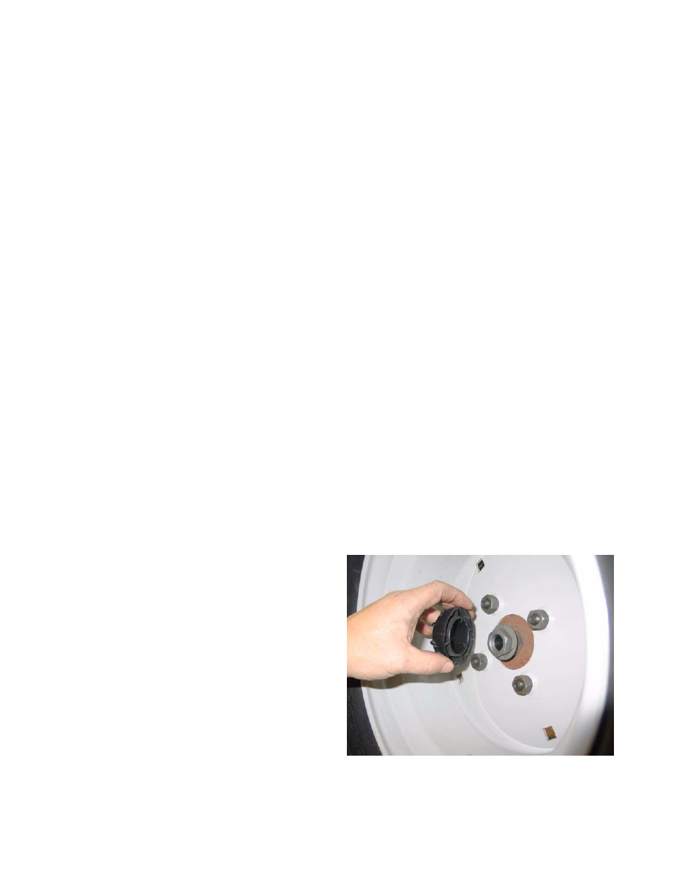
34.6. Remove the rear hub caps, then the rear wheels
using a 3/4” wrench. See Figure 34.6.
Figure 34.6