Cub Cadet SLT1500 Series User Manual
Page 12
Series 1000 and 1500
8
5.7.
Remove the four bolts that hold the seat brack-
ets to the frame using a 1/2” wrench.
5.8.
Remove the seat to a safe location.
5.9.
Remove the hydro control pedal (or speed con-
trol pedal on CVT equipped models) using a T-
40 driver. See Figure 5.9.
5.10. Remove the brake pedal using a T-40 driver
(upper screw) and a 9/16” wrench (lower screw).
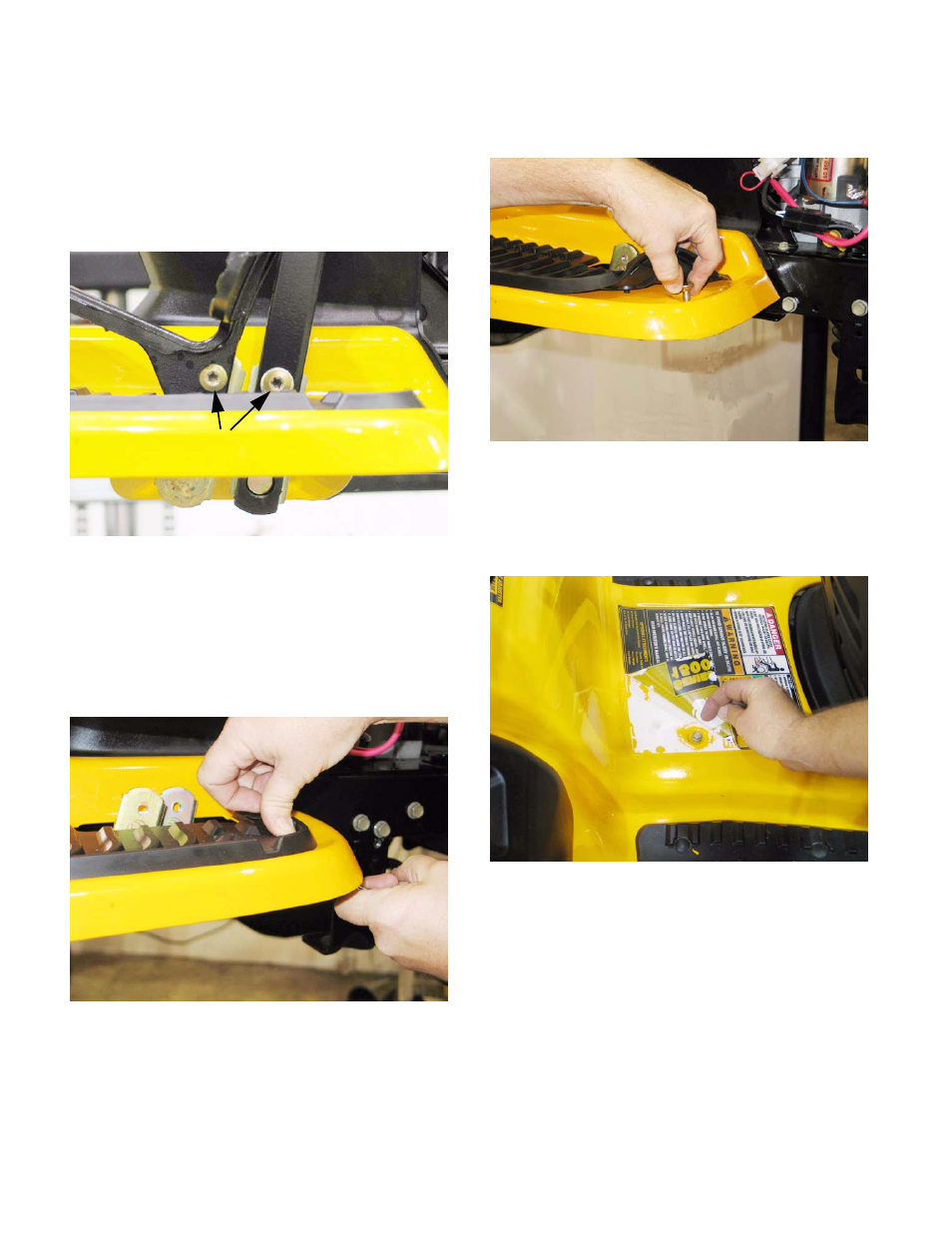
5.11. Remove the nuts from the carriage bolts that
secure the front edge of each running board to
the frame bracket that supports it.
See Figure 5.11.
•
Apply thumb pressure to the rubber foot pad,
directly above the nut / carriage bolt to hold the
square boss on the nut into the bracket, to pre-
vent rotation.
5.12. Peel-back the rubber foot pad to reach and
remove the carriage bolt. See Figure 5.12.
5.13. Carefully peel-up each rear corner of the larger
instruction label located between the foot pads,
revealing two screws that hold the fender
assembly to the frame. See Figure 5.13.
NOTE: If the previous steps are done with care,
the label can be reapplied, using some spray-on
contact adhesive if necessary.
•
If the label shows signs of becoming damaged
by the peeling-back process, it should be
replaced during reassembly.
•
To identify and order a replacement label, note
the number printed on the lower right corner of
the label (“S32484 AC” typical). That number,
with a 777 prefix (777-S32484 AC) is usually the
part number of the label.
Figure 5.9
T-40 Screws
Figure 5.11
Figure 5.12
Figure 5.13