Warning – Cub Cadet 190-291-100 User Manual
Page 9
9
WARNING
Before installing the mower deck, place the
PTO switch in the “OFF” position, engage the
parking brake lever, and turn ignition key to the
“OFF” position. ALWAYS stop the engine after
utilizing the tractor hydraulic lift system. When
handling the mower deck, be careful not to cut
yourself on the sharp blades.
2.
Slide the deck under the tractor until the slots of
the LH and RH rear deck brackets align approxi-
mately with the tractor lift links (See Figure 9).
3.
Pull outward and cock the deck support pins in the
rear deck brackets so that both spring-loaded pins
are held in the disengaged position against the
inner surface of the deck brackets (See Figure 9).
Figure 9
4.
Use the tractor lift system to lower the lift links.
NOTE: If installing the deck on a tractor with the
deck downstop feature, make certain the
downstop is in the lowered position (Refer to
Section 1 step B-1).
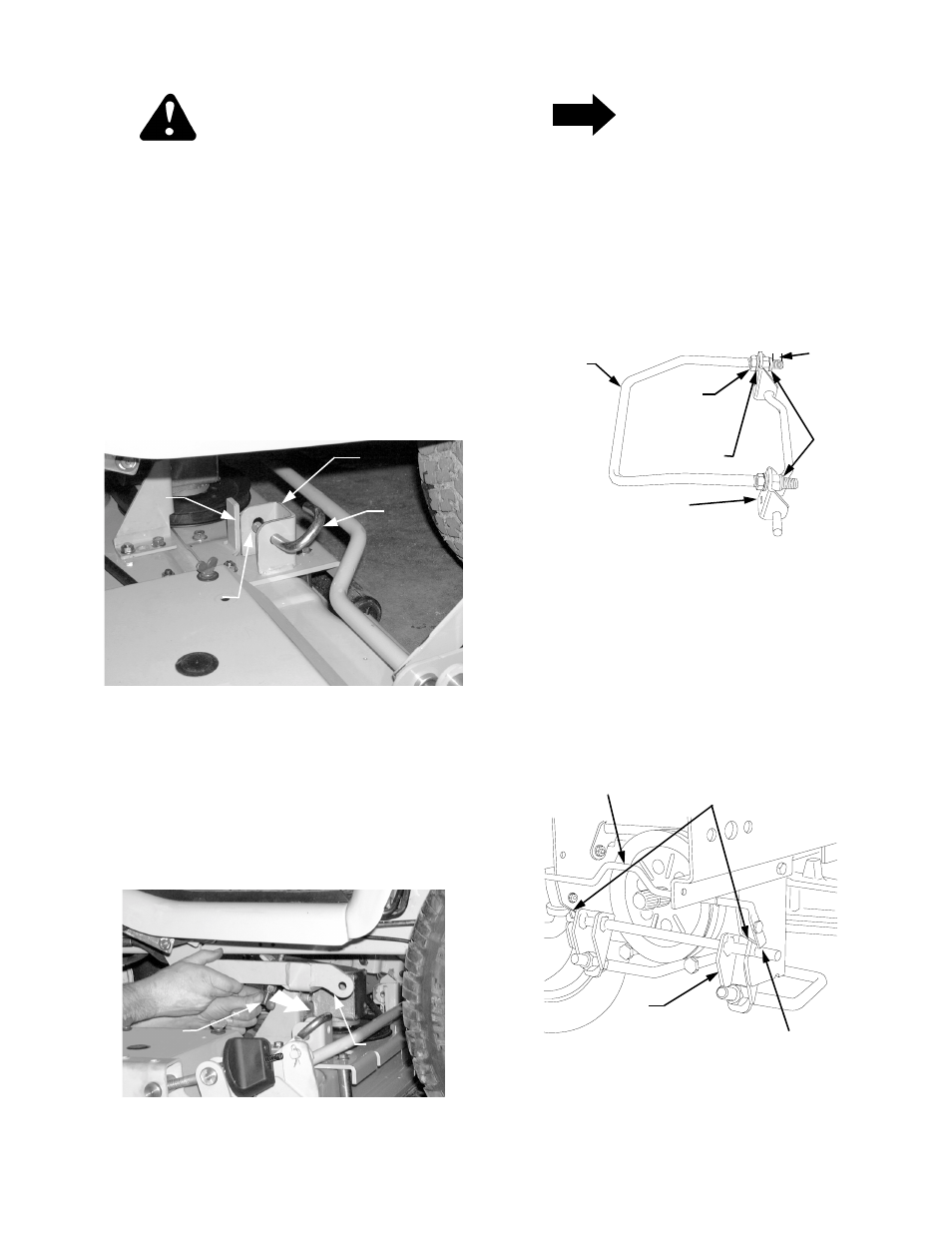
5.
Unlock the left lift link by sliding the left lift rod fully
rearward in the slot of the lift link (See Figure 10).
Figure 10
NOTE
The following step 6 applies only to the initial
installation of the mower deck on the tractor.
6.
Loosen the hex jam nuts on the front lift bracket/
rod assembly and back off (unscrew) the hex lock
nuts until approximately 1/2 inch from the ends of
the threads (See Figure 11).
Figure 11
7.
From the front of the tractor, slide the outer pins of
the front lift bracket into the latch receiver slots of
the tractor. Press the lift bracket rearward until
both sides are firmly captured in the latch receivers
by the quick latch rod (See Figure 12).
Figure 12
REAR DECK
BRACKET
DECK
SUPPORT
PIN
PIN LOCKED IN
DISENGAGED
POSITION
SLOT
LEFT
LIFT
ROD
LH LIFT
LINK
FRONT
LIFT
FRONT LIFT
BRACKET
HEX
LOCK WASHER
HEX
LOCK
NUTS
JAM
NUT
ROD
QUICK LATCH ROD
LATCH RECEIVER SLOTS
FRONT
LIFT
BRACKET
CAPTURE IN
RECEIVER SLOTS