Warning – Cub Cadet 190-291-100 User Manual
Page 15
15
4.
Reposition the caster wheels and roller so that
they are appoximately 1/2 inch above the ground.
5.
For subsequent minor adjustments from this
position, use the tractor lift system to raise the deck,
then turn the adjustment knob as necessary to
attain the desired height setting (one full turn
equals approximately 1/4"). Reposition the caster
wheels and rollers if necessary.
NOTE: To use the caster wheels/rollers for setting the
cutting height on tractors equipped with the deck
downstop, make certain to lower the downstop using
the height adjustment knob. Then follow the previous
instructions for setting the cutting height using the
caster wheels and rollers.
Figure 26
RAISE
LOWER
HEIGHT
ADJUSTMENT
KNOB
SECTION IV. MAINTENANCE
A. CLEANING AND BLADE CARE
WARNING
Before performing any maintenance, place the
PTO switch in the “OFF” position, engage the
parking brake lever, turn the ignition key to the
“OFF” position and remove the key from the
switch. When servicing the mower deck, be care-
ful not to cut yourself on the sharpened blades.
Clean the underside of the mower deck at the end of
the mowing season or when buildup of cut material on
the underside is noticed.
Once a month remove the thumb screws, bell washers,
and belt covers (Refer to Figure 29) to remove any accu-
mulated grass clippings from around the spindle pulleys
and V-belt. More often when mowing tall, dry grass.
The cutting blades must be kept sharp at all times. Sharp-
en the cutting edges of the blades evenly so that the
blades remain balanced and the same angle of sharp-
ness is maintained. If the cutting edge of a blade has
been sharpened to within 5/8 inch of the wind wing radius
(See Figure 27), it is recommended that new blades be
installed. New blades are available at your authorized
dealer.
Figure 27
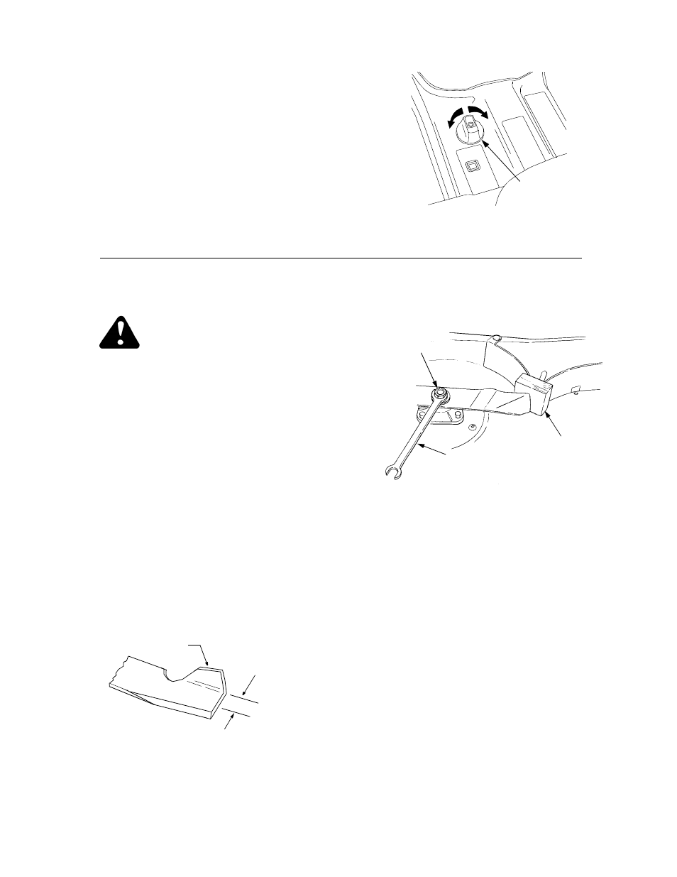
When removing the blades, use a 1-1/8 inch wrench to
hold the head of the spindle bolt while loosening the
hex nut securing the blade. A block of wood may be
placed between the deck housing and the cutting edge
of the blade to assist in removal of the hex nut (Refer
to Figure 28).
Figure 28
When reinstalling the blades, be sure they are installed
so that the wind wings are pointing upward toward the
top of the deck. Tighten the nuts to 90 to 110 ft-lbs.
(122 to 149 N·m).
After replacing the blades, apply grease to the
exposed threads at the bottom of the spindle bolts to
prevent rust buildup.
B. LUBRICATION
After every 10 hours of operation and/or before putting
the deck into winter storage, lubricate the spindle
assemblies and the spindle belt idler arm with 251H EP
grease or an equivalent No. 2 multipurpose lithium
grease. The lube fitting for the outer spindles can be
accessed by removing the button plugs in the belt
covers. Use grease liberally. Excess grease will be
expelled from the inverted upper seals of the spindle
assemblies. Listen for the muffled crackling noise of
grease being expelled through the seal to indicate the
spindle assembly is fully greased (Refer to Figure 29).
Apply grease to all other lube fittings after every 50
hours of operation. Refer to LUBRICATION GUIDE.
WIND
WING
5/8" FROM
RADIUS
HEX NUT
1-1/8" WRENCH
WOOD BLOCK
IN POSITION