Warning – Cub Cadet 190-291-100 User Manual
Page 12
12
SECTION III. ADJUSTMENTS
DECK LEVELING ADJUSTMENTS
NOTE
Tractors built Mfg. Code 1K060G and after are
equipped with a deck downstop feature which
can be used to set the downstop position of the
mower deck, regardless of whether the deck
caster wheels contact the ground.
The 60" mower deck is equipped with ground following
front caster wheels and is designed to be operated with
the caster wheels and rear rollers on the ground.
However, if the deck is being installed on a tractor
equipped with the downstop feature, the deck can be
suspended off the ground by utilizing the deck height
adjustment knob to set the downstop position. In either
case, to ensure an even cut on all types of terrain, the
mower deck should be properly leveled. The side to
side leveling procedure will result in the left and right
blades having corresponding cutting-edge-to ground
measurements within 1/16 inch of each other. Also,
the cutting blades will have a downward tilt toward the
front of the tractor of approximately 1/8 inch. To level
the mower deck, proceed as follows:
WARNING
Before making any adjustments, place the PTO
switch in the “OFF” position, engage the parking
brake lever, and turn the ignition key to the “OFF”
position. When adjusting the mower deck, be
careful not to cut yourself on the sharp blades.
A. SIDE TO SIDE LEVELING ADJUSTMENT
NOTE: Check for proper tire inflation before checking
and/or making a leveling adjustment.
1.
Position the tractor on a hard, level surface, and
use the tractor hydraulic lift system to raise the
deck to its highest position. Stop engine.
Figure 18
2.
To prevent contact with the surface below, adjust
the front caster wheel arms and rear rollers to their
highest setting (lowest deck setting). If necessary,
refer to C. SETTING THE CUTTING HEIGHT.
3.
Carefully rotate the outer cutting blades so that
they are positioned perpendicular to the tractor
frame (See Figure 18).
4.
Referring to Figure 19, measure and record the
distance from the level surface to the outer-most
cutting edge of the right blade. Repeat this step for
the left blade. If the two blade heights are not with-
in 1/16 inch, the deck must be leveled. Note wheth-
er the left blade had the larger or smaller distance
between the cutting edge and level surface. If the
two blade heights are within 1/16 inch, proceed to
step B. FRONT LIFT ROD ADJUSTMENT.
Figure 19
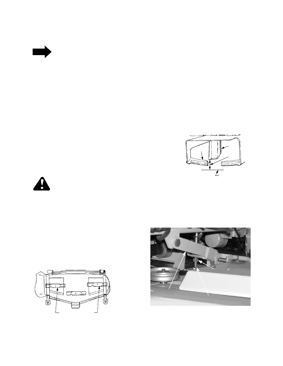
5.
Side to side leveling is attained by adjusting the
hex lock nut on the bottom of the LH lift rod,
located below the LH lift link (See Figure 20).
Figure 20
6.
Turn the hex lock nut upward (tighten) on the
threads of the lift rod to raise the left side of the
mower deck. Turn the lock nut down (loosen) on
OUTER BLADES
PERPENDICULAR TO FRAME
2
3
1
4
1.
Finger guard
2. Blade
3. Hard Level Surface
4. Measure This Distance
HEX LOCK NUT
LH LIFT ROD
LH LIFT LINK