Figure 24, Figure 25 – Cub Cadet 190-291-100 User Manual
Page 14
14
2.
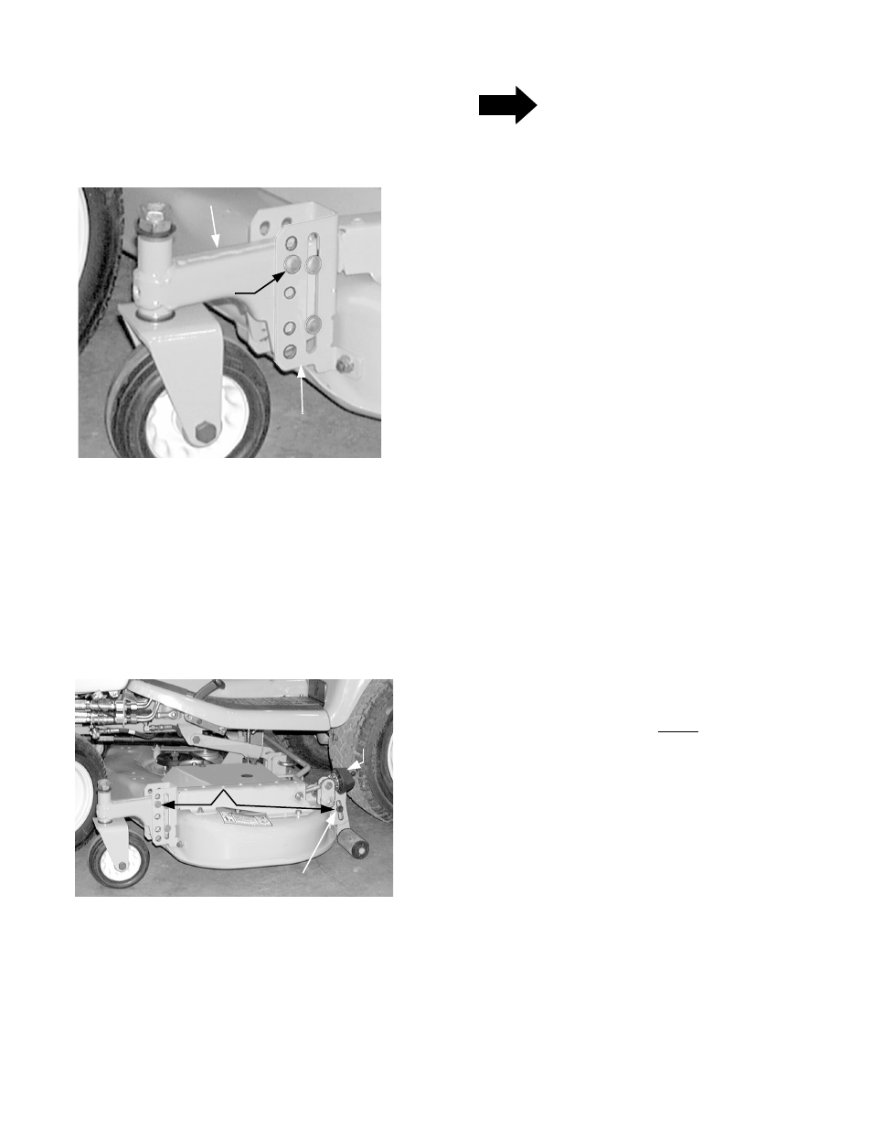
Remove the internal cotter pin, flat washer, and ad-
justment clevis pin from the height adjustment
bracket. Position the caster wheel arm in the desired
height setting and insert the adjustment clevis pin
(See Figure 24). Secure with the flat washer and in-
ternal cotter pin. Repeat for other side.
Figure 24
3.
From the left/rear of the deck, pull the adjustment
knob rearward to disengage the detent pin of the
knob from the hole in the detent hub. While holding
the knob rearward turn the roller adjustment knob
as necessary to align the shoulder bolt in the roller
pivot link with the corresponding height index
setting on the roller guide bracket (See Figure 25).
Figure 25
4.
Release the knob and turn as necessary to align
the detent pin with the nearest hole in the hub.
Make certain the pin is fully engaged in the hole
(See Figure 7 on Pg. 8).
NOTE
Because the weight of the mower deck may
cause some settling of the roller linkage, the
cutting blades should be measured to ensure
they are level or up to 1/8" lower in the front. If
the mower deck has been properly leveled per
the previous instructions, measuring just the
right hand cutting blade is sufficient.
5.
Carefully rotate the outer cutting blades so that the
ends of the right blade point to the front and rear of
the tractor (Refer to Figure 21).
6.
Lower the deck to level surface below.
7.
Holding the chute deflector upward, measure the
distance between the front most cutting edge of
the blade and the surface. Repeat for the rear most
cutting edge and compare the two measurements.
a.
If the front measurement is the same as, or up
to 1/8" less than the rear measurement, no ad-
justment is required.
b.
If the rear measurement is greater than 1/8"
higher than the front measurement, turn the
roller adjustment knob clockwise as needed to
raise the roller and achieve the specified pitch
of the deck.
c.
If the front measurement is greater than the
rear measurement, turn the roller adjustment
knob counterclockwise as needed to lower the
roller and achieve the specified pitch of the
deck. Remember the detent pin of the adjust-
ment knob should engage the nearest hole in
the detent hub.
USING HEIGHT ADJUSTMENT KNOB — TRAC-
TORS WITH DECK DOWNSTOP ONLY
Each full rotation of the height adjustment knob equals
approximately a 1/4 inch adjustment in the deck height
setting, and there are four detent positions per rotation.
Initially set the deck downstop as follows (Refer to
Figure 26):
1.
To remove the weight of the deck from the downstop
arm, use the tractor lift system to raise the deck. Ad-
just the caster wheels and rollers to their highest po-
sition.
2.
Fully lower the deckstop by continuously turning
the height adjustment knob counterclockwise.
3.
Use the tractor lift system to lower the deck to the de-
sired height setting, then turn the adjustment knob
clockwise until it stops turning freely. Turn the knob to
nearest detent position.
1
2
3
4
5
CASTER WHEEL ARM
HGT. ADJ.
BRACKET
INDEX HOLE POSITION 1 = LOWEST DECK SETTING
INDEX HOLE POSITION 5 = HIGHEST DECK SETTING
ADJUSTMENT
CLEVIS PIN
1
2
3
4
5
1
2
3
4
5
SET IN
POSITION 3
SHOULDER BOLT
ROLLER
ADJ. KNOB