Warning – Cub Cadet 190-291-100 User Manual
Page 6
6
SECTION I. TRACTOR AND DECK PREPARATION
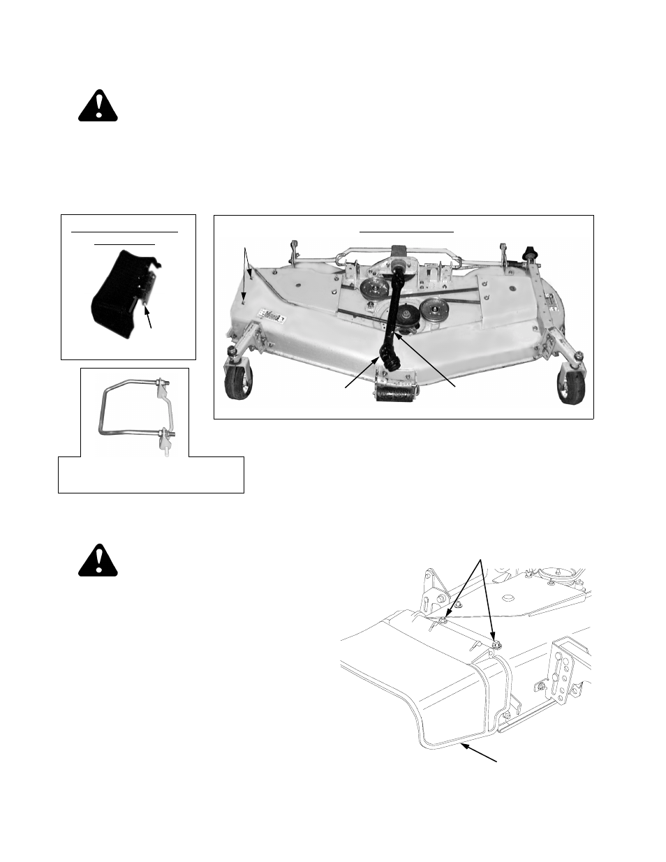
WARNING
When handling the mower deck, be careful not
to cut yourself on the sharp blades.
Remove the top and break down the sides of the crate
to remove the deck components from the shipping
container. Cut the tie straps securing the chute
deflector assembly and front drive shaft to the deck
assembly. Remove all padding material from the drive
shafts. Refer to Figure 1.
NOTE: The mower deck front lift bracket/rod assembly
is shipped on the tractor. If not already done, cut the tie
strap securing the front lift bracket/rod assembly to the
front of the tractor frame. Pull the center of the tractor’s
quick latch rod downward to remove the lift bracket as-
sembly from the tractor.
Figure 1
A. DECK PREPARATION
WARNING
Do not operate the mower deck without the
chute deflector installed and in the down
position.
Install the chute deflector onto the right side of the deck
over the discharge chute opening as follows:
1.
Remove the two carriage bolts and hex flange lock
nuts from the deck housing at the discharge chute
opening.
2.
Position the chute deflector assembly on the deck
above the discharge opening, aligning the two
holes in the hinge bracket with the holes in the
deck housing.
3.
Insert the carriage bolts from the underside of the
deck and through the holes in the hinge bracket.
Secure with the two hex flange lock nuts (See Fig-
ure 2).
Figure 2
CHUTE
Hex Flange Lock Nuts
& Carriage Bolts
DEFLECTOR
FRONT LIFT BRKT/ROD ASS’Y.
— SHIPPED ON TRACTOR
CHUTE DEFLECTOR
ASSEMBLY
HINGE
BRACKET
FRONT DRIVE
SHAFT
REAR DRIVE
SHAFT
DECK ASSEMBLY
FASTENERS