Network video server/ip camera user manual – COP-USA WS08 User Manual
Page 10
Network Video Server/IP Camera User Manual
10
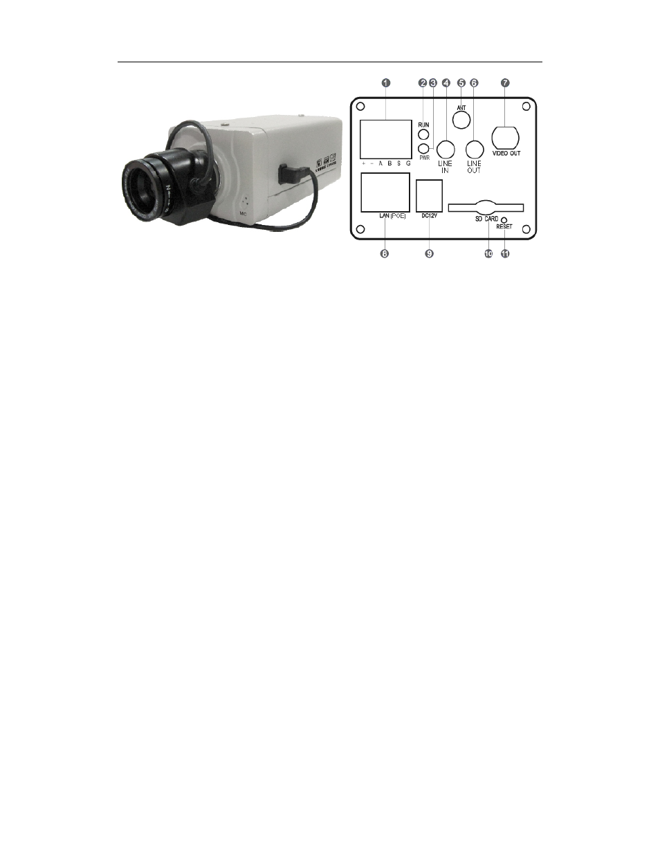
Interface description:
1.『+,-』RS485 interface
『
A,B』alarm output interface, switching output, opened in normal and closed in alarm linkage.
『
S,G』alarm input interface, normal open or normal close probe can be connected,【S,G】is a
group of alarm input.
2.『RUN』system run indicator lamp, flashing indicating normal running of system
3.『PWR』is power supply indicator lamp.
4.『LINE IN』audio input, connecting to active device.
5.『ANT』antenna interface (WIFI/3G antenna)
6.『LINE OUT』audio output, connecting active device or passive device
7.『VIDEO OUT』analog video output interface (not supported in high definition series IP Camera)
8.『LAN(POE)』RJ45 socket of standard network (optional POE function)
9.『DC12V』connect to 12V DC through voltage stabilizer, please use matching voltage stabilizer
power supply.
10.『SD CARD』SD card interface, high speed SD card can be inserted, support up to 32G.
11.『RESET』reset button, it is used to restore factory default parameters of device, including IP
address and user password.
4) Definition for the interface of network PTZ hemisphere interface: