Checkline TS2P User Manual
Page 8
– 7 –
3.3 Options
Code DC Analog output 0 - 10 V DC
Code MA Analog output 4 - 20 mA
3.4 Initial Setup
• Install the sensor at the desired measuring location.
• Connect the sensor to the supplied or existing display unit. The pin assignment
of the 5-pin connector located on the rear side of the sensor is described in
section 3.2.
• If the material path is other than vertical or if the process material deviates
significantly from the factory calibration material, you need to carry out
ZERO Adjustment and GAIN Adjustment as described in sections 4.1 and
4.2 before starting measurement.
• Allow approx. 10 minutes for thermal stabilization of the sensor.
• Thread the process material through the measuring and guide rollers, following
the material path symbol on the front of the sensor.
1
2
3
4
5
6
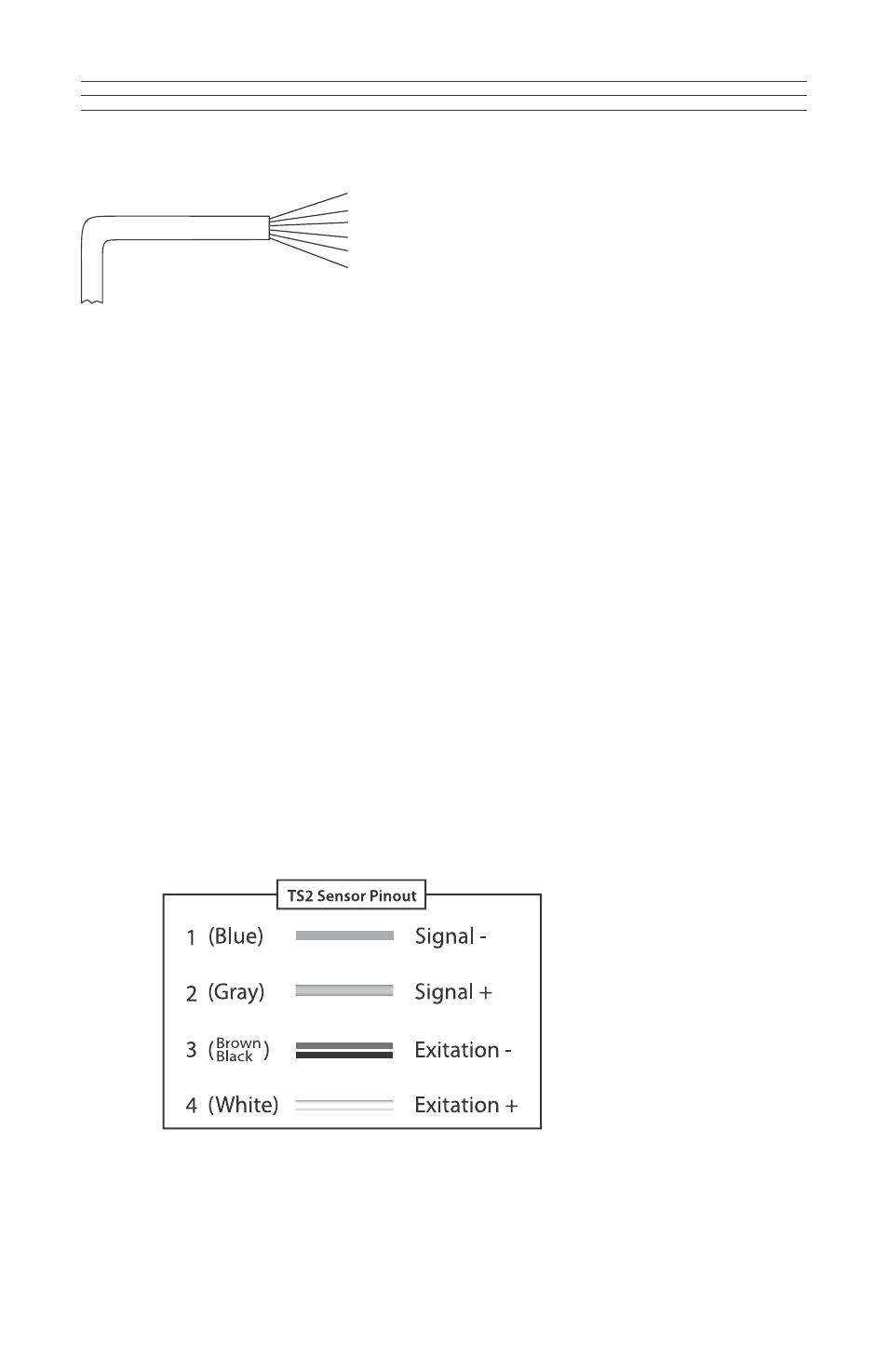
Wire assignment of cable TS2-CABLE:
1 (white) Vcc + 15 to 24 V DC regulated
2 (black) Ground
3 (brown) Ground
4 (blue) Signal output –
5 (grey) Signal output +
6 (black) Shield (thick black wire)
}
}
Joined