Checkline TI-45N User Manual
Page 7
TI-45N Operating Instruction Guide
7
4.4
Turning The Power ON
After connecting the probe as described in section 4.4, turn on the power by
pressing the
POW
key. The current acoustic velocity setting will be momentarily
displayed prior to entering the Measurement Mode (Mode H). The display should
then read 0.000 inch (or 0.00 mm).
If the Good Coupling Indicator is flashing on and off, the red transmit connector
of the probe is not connected properly.
4.5
Turning The Power OFF
The Power will turn off automatically after three (3) minutes of non-use. To
manually turn off the power, press & hold the
POW
key for 3 sec., then release.
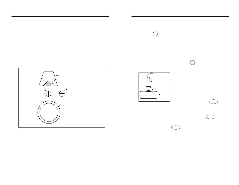
4.6 Zero Adjustment
This operation adjusts the zero point of the probe.
Zero adjustment data is stored in the instrument. It
is recommended that the zero adjustment data be
refreshed once a day, preferably before starting the
day’s work.
1. Apply couplant on the test plate surface and
place the probe on it.
2. Make sure the probe is in good contact with the
test plate surface and press the
ZERO
switch.
3. The zero adjustment procedure takes place and the display reads 0.197" or
5.00 mm when the process has been successfully completed.
NOTE: When the sonic velocity is set to a value other than 5390 m/s, the
display reads 0.197" or 5.00 momentarily when the
ZERO
switch is
pressed. Zero adjustment is nonetheless proceeding correctly.
If the material to be tested is significantly larger or smaller than 0.197"
or 5.00mm, and the ZERO switch is pressed, the display will read ----
and the zero adjustment process becomes invalid. In this case, the zero
adjustment should be made on a sample of known thickness of the test
material itself.
4.7 Using Couplant Fluid
Apply couplant fluid to the measuring surface before measurement. The couplant
eliminates air between the probe and test surface, promoting the transmission of
the ultrasonic pulse.
NOTE: Never use organic solvents, including thinners and alcohols.
The surface must be cleaned of couplant after measurement.
Probe
Te st plate
Thickness
gauge
TI-45N Operating Instruction Guide
18
7.3
Measurement Of Pipes Or Cylindrical Objects
When using a TI-45N Gauge to measure the wall thickness of pipes it is
highly recommended that the optional spring-loaded shell attachment be used.
It is supplied with a v-notch at the bottom of the shell attachment which greatly
helps maintain a stable right-angle probe position during measurement on
cylindrical surfaces.
Pipes with outer diameters less than 1 inch (25 mm) cannot be measured.
The orientation of the probe is important when measuring wall thickness of
pipes. The centerline of the probe face (separating the two sections) should
be arranged so that it is parallel to the length of the pipe as illustrated below.
Removable Shell Attachment (optional)
V-Notch
Probe
Pipe Wall
Open End
of Pipe
INCORRECT
Positioning of
Centerline of
Probe
CORRECT
Positioning of
Centerline of
Probe