Checkline TI-25LT User Manual
Page 6
– 6 –
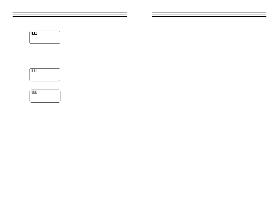
The eight vertical bars shown form the Stability
Indicator. When the TI-25LT is idle, only the
left-most bar and underline will be illuminated.
When a measurement is being performed, six or
seven bars should be illuminated indicating that it is a stable measurement.
If fewer than five bars are illuminated, the TI-25LT is having difficulty
obtaining a stable and reliable measurement and the thickness value shown
should be ignored, as it is most likely erroneous.
When the “IN” indicator is illuminated,
the TI-25LT is displaying a wall thickness
measurement in INCH units.
When the “MM” indicator is illuminated,
the TI-25LT is displaying a wall thickness
measurement in MM units.
3.6 Probe Zero Plate
When first connecting the probe supplied with the TI-25LT, the user should
perform a “Probe Zero” as described in Section 4.3. The Probe Zero Test
Plate is used for this task. It is located on the top edge of the gauge as
shown in the photo below. It also serves as the battery compartment cover
Note:
The thickness of this plate is not imporatnt, and it should not be
used as a Calibration Test Plate. A precision 4-step Test Block is optionally
available for this purpose.
1.8.8.8.8
+
IN MM/
µ
s
1.8.8.8.8
+
IN
MM/
µ
s
1.8.8.8.8
+
IN
MM
/
µ
s
– 11 –
6 .0
M EASU RI N G PROCEDU RE
After performing the Probe Zero operation, the gauge is ready to take wall
thickness measurements.
1. Turn on the power by pressing the ON/OFF key.
2. Plug the probe cable into the receptacle at the top of the gauge.
3. Place a small amount of coupling fluid on the surface to be
measured.
4. Grasp the probe by the molded rubber grip and place it on top
of the material surface. Apply moderate pressure to the top
surface of the probe with your index finger or thumb to
stabilize the probe and to keep the wearface seated flat against
the measurement surface.
5. The gauge will display the thickness of the steel wall along with the
Stability Indicator showing the relative stability of the reading.
6. Repeat steps #3 – #5 as required.
6.1 General Notes On Measurements
1. When the probe is removed from the sample after a
measurement, the last reading will be retained on the display.
2. If fewer than five bars of the Stability Indicator are illuminated,
the thickness reading displayed is most likely inaccurate.
3. Occasionally, a small film of couplant will be drawn out between
the probe and the surface as the probe is removed. When this
happens, the TI-25LT may perform a measurement that is larger or
smaller than it should be. This phenomenon is obvious when one
thickness value is observed while the probe is in contact with the
material, and another value after the probe is removed.
4. The gauge will automatically power off after 5 minutes of non-use.
5. The following surface conditions can prevent accurate
measurements (refer to section 4.6 Preparation Of The Surface):
• Rough or heavily pitted surface
6. If two materials are press-fitted or laminated together, the gauge
will only measure the thickness of the sample that contacts the
probe.