Page 7, Page 2 – Checkline ESH User Manual
Page 2
page 7
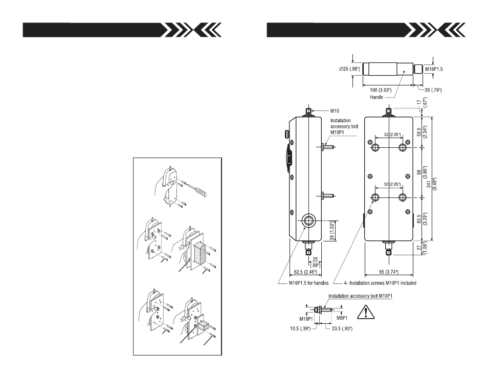
DIMENSIONS
Use this bolt only!
page 2
GENERAL OPERATION
1. Press (or rotate for Model PSH/ESH) Peak Switch OFF.
2. Hand tighten (no tool!) attachment to the measuring shaft.
3. Rotate Tare Ring to read “0” to tare the weight of attachment and
measuring shaft orientation.
4. Begin measuring.
Real Time Mode:
the Peak Switch is OFF and the gauge dis-
plays force as it changes. During Real Time Mode, you can hold a
critical reading by turning the Peak Switch to the ON position.
Peak Mode:
the Peak Switch is ON and the gauge will retain
highest reading taken which will not change until a higher
value is measured. Turn the Peak Switch OFF to zero the gauge
and turn it ON again to measure Peak values.
MOUNTING
When mounting IMADA mechani-
cal gauges to IMADA test stands,
hold the gauge firmly and unscrew
the 4 screws in back, making sure
the case does not separate. (FIG.1)
AP-002 adapter plate mounts IMADA
mechanical gauges to IMADA test
stands. Align plate and gauge holes
and insert the 4 long screws sup-
plied to attach gauge. Then utilize
the 4 PEM nuts on the adapter plate
to mount to IMADA test stands
with the mounting bolts supplied.
AP-001 adapter plate mounts IMADA
low capacity gauges to most other
brands of test stands. Use the 4
screws (supplied) to mount the
IMADA gauge to the AP-001 adapter
plate. Then utilize the 2 PEM nuts
on the AP-001 adapter plate to
mount to other brands of test stand.
REMOVE CASE
SCREWS
AP-001 ADAPTER PLATE
WITH 2 PEM NUTS
AP-002 ADAPTER PLATE
WITH 4 PEM NUTS
PEM NUT
LONGER SCREWS
MOUNTING BOLTS
PEM NUT
LONGER SCREWS
MOUNTING BOLTS
MOUNTING PS/FB/MF
FIG.1
Speciications subject to change without notice.