0 setup – Checkline QB-LED User Manual
Page 6
– 5 –
3.0 SETUP
3.1 Connectors (see Fig. 1)
3.2 Set-up steps
Please follow the steps below when setting up the device:
1. Charge the device by plugginh the charger into the CHARGE (A) socket to the
rear of the device (see Fig. 1)
2. Direct the device at a moving object and switch it on. Turn the selector switch (E)
one notch to the left to “FREQUENCY.”
The device will start to flash immediately. For this reason, do not
direct it at people or animals.
NOTE: The device will flash at the frequency that was set most recently. The display
shows the selected flash frequency in the unit that was set most recently (rpm, Hz or
FPM). If the flash frequency coincides with the frequency of the motion, a static
image appears.
3.3 Connect the trigger
The device has the option of being externally triggered.
DO NOT trigger the device with signals in excess or 300,000 FPM.
Material damage may occur.
NOTE: Use only original material from the manufacturer to connect the trigger signal.
The trigger input is isolated and is suitable for PNP
and NPN signals. A trigger plug suitable for this
input socket is included with the device.
1. Plug the trigger plug into the input socket
INPUT (B).
2. Screw in trigger plug.
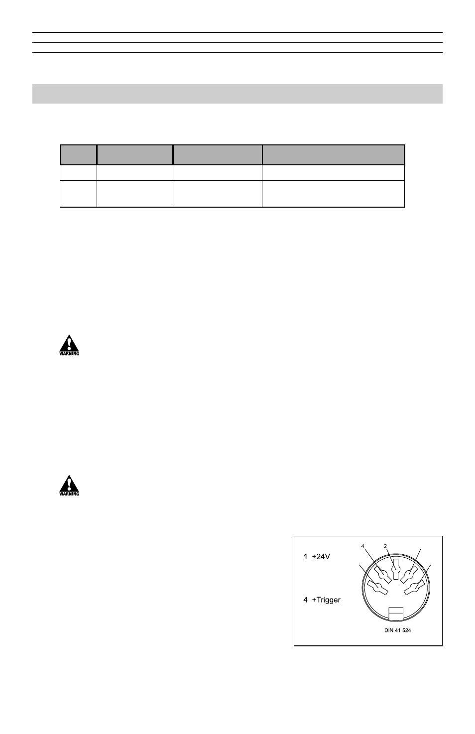
3. Assign the connection socket as per Fig. 3.
NOTE: The device must be manually switched
between external and internal trigger signals (see
How select an internal/external trigger, page 9).
(EN 60130-9)
1
5
3
2 nc
3 GND
5 -Trigger
Fig. 3 - Assignment of the
connection socket.
No.
Marking
Term
Description
(A)
CHARGE
Charging Socket
Device is charged using a charger
(B)
INPUT
Input socket
Input for external tripper/24 V
power supply