Mounting bracket adjustment, Specifications installation – Checkline DT-5TG User Manual
Page 2
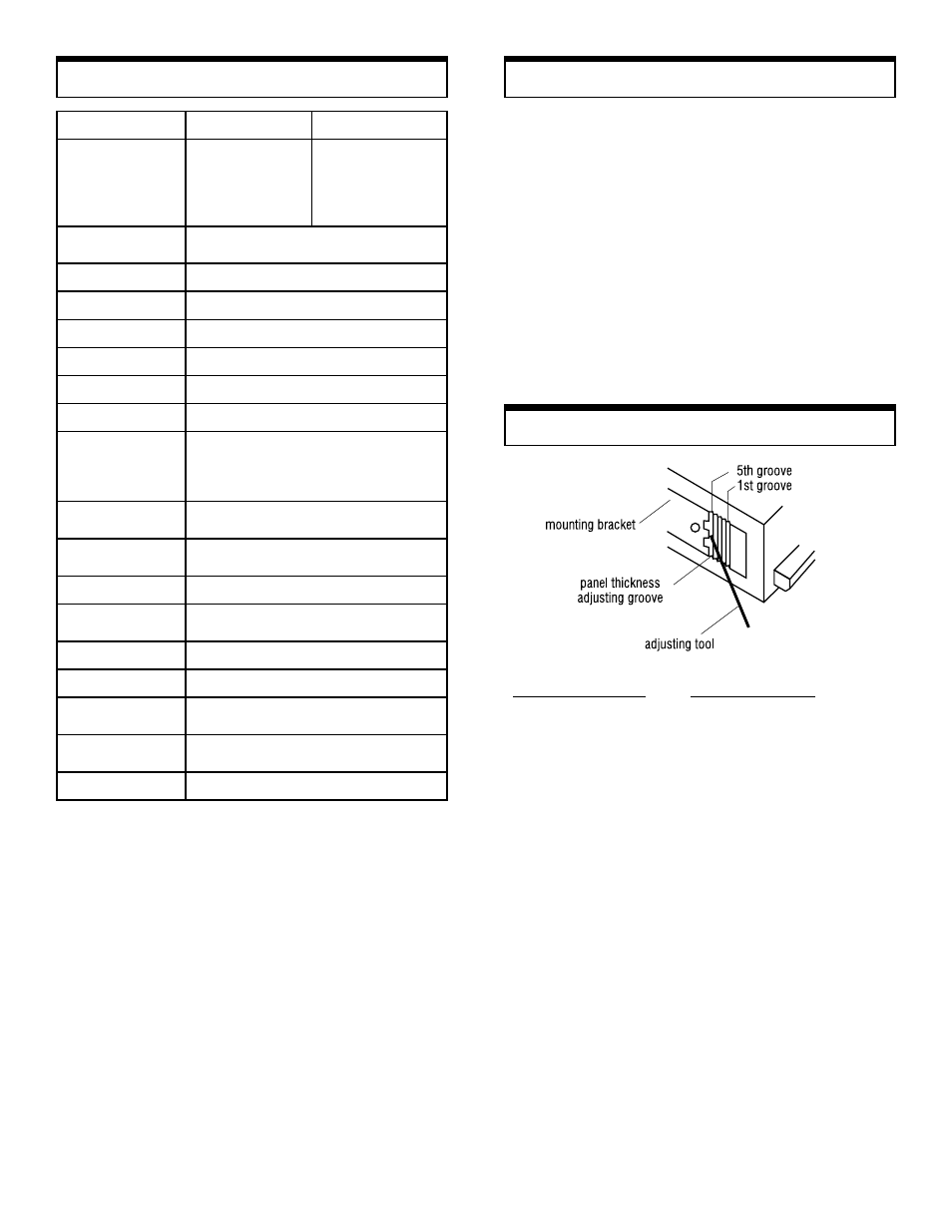
Mounting Bracket Adjustment
Panel Thickness
Thickness of Panel
Adjusting Groove
1.2 – 1.6 mm
5th groove (factory setting)
1.8 – 2.5 mm
4th groove
2.8 – 3.6 mm
3rd groove
4.0 – 4.5 mm
2nd groove
5.0 mm
1st groove
2
Specifications
Installation
Mounting Unit
Our 1/8 DIN case design eliminates the need for brackets
and screws for installation. With the tachometer in a level
position, insert it into the panel cutout. Gently push the
face of the unit until the front bezel locks into place. If the
tachometer case is loose, adjust the integral bracket with
the enclosed tool.
Removing unit
From the rear of the tachometer, alternately push the unit
from the left and right. This will free it for easy removal.
Function
Function
Function
Function
Rate Measurement
Rate Measurement
Rate Measurement
Rate Measurement
Elapsed Time Counter
Elapsed Time Counter
Elapsed Time Counter
Elapsed Time Counter
Display Range
Display Range
Display Range
Display Range
0.0000–9.9999
0.000–99.999
0.00–999.99
0.0–9999.9
0–99999
99.99 sec.
99 min. 59 sec.
99 hours 59 min.
Measuring range
Measuring range
Measuring range
Measuring range
10–99999 rpm (at 1p/r), 0.2–30000 rpm
(at 60p/r)
Update Time
Update Time
Update Time
Update Time
0.25, 0.5, 1, 2, 4, 8, 16 sec., selectable
Display
Display
Display
Display
5-digit LED (0.56" or 14.2 mm high)
Time base
Time base
Time base
Time base
Controlled by a 4.194304 MHz crystal
Accuracy
Accuracy
Accuracy
Accuracy
±0.008% ± 1 digit
Measuring system
Measuring system
Measuring system
Measuring system
CPU controlled
Input no. of p/r
Input no. of p/r
Input no. of p/r
Input no. of p/r
1–9999 (programmable)
Input signal
Input signal
Input signal
Input signal
characteristics
characteristics
characteristics
characteristics
Sine wave–max frequency 10 kHz
Square wave–max frequency 30 kHz
open collector
Contact closure–max frequency 20 Hz
Input signal
Input signal
Input signal
Input signal
amplitude
amplitude
amplitude
amplitude
Sine wave (0.3–30 VP–P)
Square wave LO: 0–1.5 V, HI 4–30 V
Input impedance
Input impedance
Input impedance
Input impedance
10 k ohms for magnetic pickup, rotary pulse
generator and proximity switch only
Voltage output
Voltage output
Voltage output
Voltage output
12 VDC ±5% (50 mA max) to power sensors
Applicable Sensors
Applicable Sensors
Applicable Sensors
Applicable Sensors
rotary pulse generator, magnetic pickup,
proximity switch, retro-reflective
Ambient temperature
Ambient temperature
Ambient temperature
Ambient temperature
32°–113° F (0°–45° C)
Power consumption
Power consumption
Power consumption
Power consumption
1W (5W when using optional modules)
Voltage requirements
Voltage requirements
Voltage requirements
Voltage requirements
9–35 VDC
Dimensions
Dimensions
Dimensions
Dimensions
3.46"L x 1.88"H x 3.78"W (88L x 48H x 96W
mm), includes bezel, fits 1/8 DIN cutout
Weight
Weight
Weight
Weight
0.55 lbs (250g)