Brookfield Thermosel User Manual
Page 8
Brookfield Engineering Laboratories, Inc.
Page 8
Manual No. M/94-204-I0612
Position the thermo-container and base between the viscometer stand legs and adjust the three (3)
knurled screws until the bubble is centered.
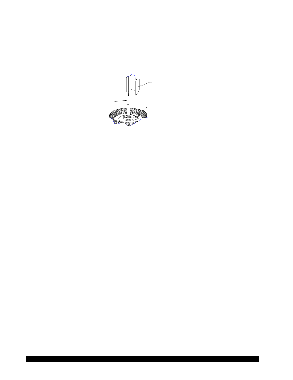
Lower the viscometer until the tips of the alignment bracket (see Figure I-1) just touch the horizontal
sur face of the locating ring, making contact directly behind the vertical curve. Raise the vis cometer,
positioning the tips of the alignment bracket about 1/16 inch above the horizontal surface behind
the locating ring. An etched line on the back of the locating ring is the 1/16 inch reference point.
SPINDLE
ALIGNMENT BRACKET
HT-69Y
LOCATING RING
Figure I-1
NOTE: Do not forcibly displace the alignment bracket!
Thermosels and Viscometers are factory-aligned prior to shipment. If viscosity measure ments are
suspect, first check system calibration using suitable viscosity standard fluids (see Appendix B).
Add the appropriate volume to the sample container (see Appendix A, Range Tables, for volume
requirement; see viscometer operating manual for calibration procedures).
• If using a spindle that requires an extension link and coupling nut, attach one end of the link to
the spindle and the other to the coupling nut. Carefully lower the spindle by the coupling nut
and link into the sample chamber. While pushing up gently on the pivot screw that protrudes
from the bottom of the viscometer, thread the coupling nut onto the viscometer. Note that the
spindle has a left-hand thread.
• If using a solid shaft (SC4-**BS) spindle, carefully lower the spindle into the sample chamber.
While pushing up gently on the spindle coupling nut that protrudes from the bottom of the
viscometer, thread the spindle onto the viscometer. Note that the spindles have a left-hand
thread.
Place the insulating cap over the sample chamber inlet.