Brookfield DV-E Viscometer User Manual
Page 10
Brookfield Engineering Labs., Inc.
Page 10
Manual No. M98-350-J0912
In case of emergency, turn off the instrument and then disconnect the electrical cord from
the wall outlet.
The safety of any system, incorporating this instrument, is the responsibility of the
assembler of the system.
The user should ensure that the substances placed under test do not release poisonous,
toxic or flammable gases at the temperatures to which they are subjected to during the
testing.
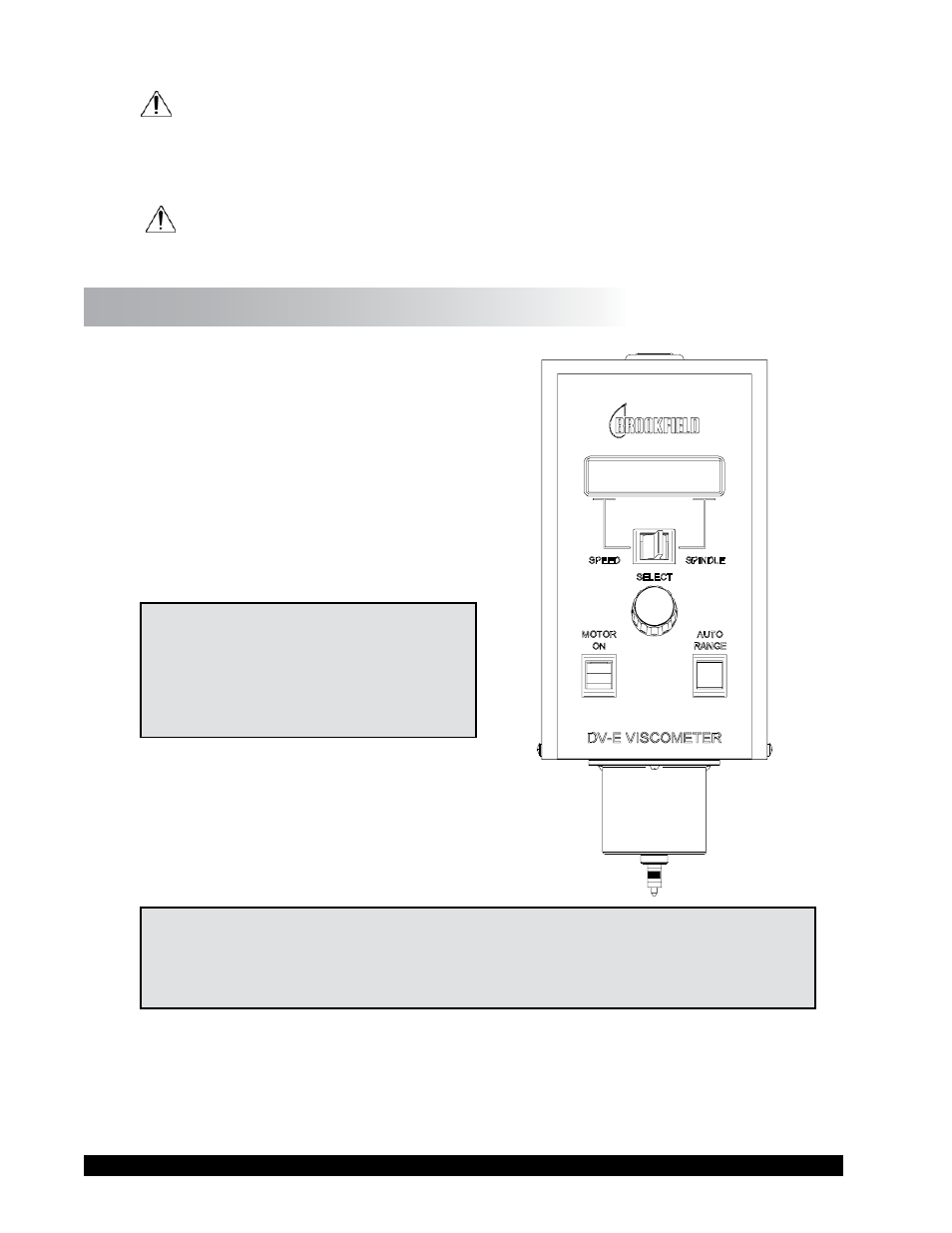
I.7 Instrument Controls
The following describes each switch’s function:
Figure I-2
MOTOR ON
Turns the motor ON or OFF.
AUTO RANGE
Presents the maximum (100% torque) viscosity
attainable using the selected spindle at the
selected speed. This value is referred to as full
scale range. The allowable error for the viscosity
measurement is ± 1% of full scale range.
Note: Pressing and holding the AUTO
RANGE key during power on
will enable the viscosity display
to be read in either CGS (cP) or
SI (mPa•s) units.
SPEED/SPINDLE SWITCH
Sets the viscometer in either speed select or spindle
select (see Table C-1 in Appendix C) mode. When
set in the left position, the operator may select
speed of rotation. When set in the right position,
the operator may select spindle.
Note: This is a three (3) position switch. We recommend that the switch be set to the
middle position when finished with spindle or speed adjustment. This will prevent
an accidental change of parameters during a test.
SELECT KNOB
This knob is used to scroll through the available speed or spindle selections (see Table C-1 in
Appendix C). This knob is active when the switch is set to the left (speed) or right (spindle) position.
Rotate the knob clockwise to increase value and counter-clockwise to decrease value.