Dip switches, Stereo link switches, Stereo link mode – Aviom Aviom16/o-Y1 User Manual
Page 17
10
Y1 A-N
et
C
Ard
U
ser
G
Uide
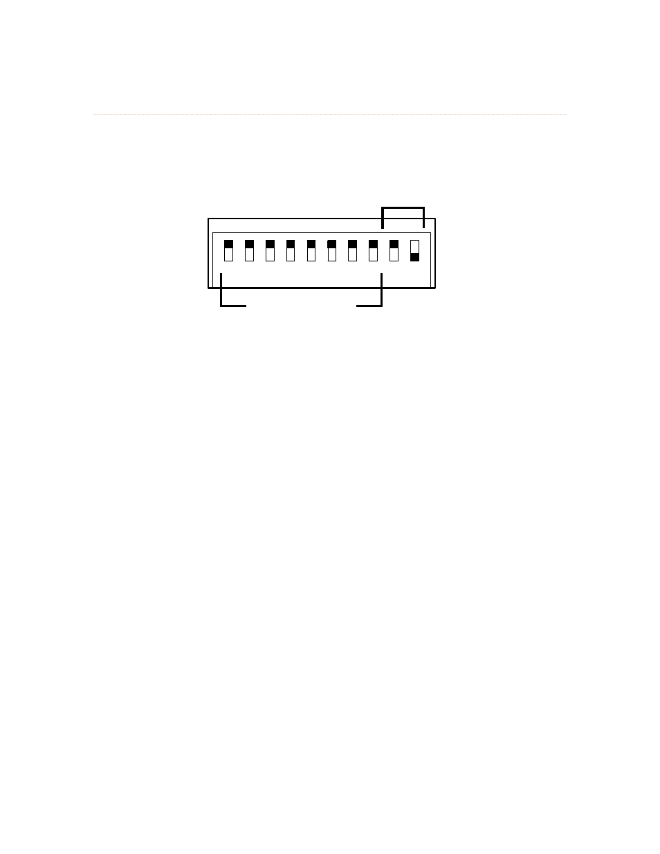
DIP Switches
The first eight DIP switches on the front of the Y1 card are used for controlling the stereo link status of the
eight possible audio channel pairs. The last two switches (9 and 10) are used to set the MY mode and to
provide access to the test function.
Stereo Link
Mode
1 2 3 4 5 6 7 8 9 10
DIP switches 1-8 control stereo links; switches 9-10 control the MY modes and the test function. Switch handles are
shown in black.
Stereo Link Switches
DIP switches 1 to 8 of are used for the stereo link function. Stereo linking is possible when using Aviom’s
Personal Mixers (A360, A-16II and A-16R) for monitor mixing. Each DIP switch controls an odd-even pair of
channels; see the list below. When the switch is set to the “On” position (down), the channels are linked as
a stereo pair. If the switch is in the “Off “ (up) position, the channels are not linked and appear in all Pro16
devices an mono channels.
Stereo link changes can be made at any time, even while the Yamaha host console is running. All connected
Pro16 A-Net devices will instantly update and reflect the change. Compatible A-Net devices such as output
modules that do not respond to stereo linking will not be affected by changes to the link status.
DIP switch 1 to 8 settings:
Switch 1 - stereo link for channels 1 and 2
•
Switch 2 - stereo link for channels 3 and 4
•
Switch 3 - stereo link for channels 5 and 6
•
Switch 4 - stereo link for channels 7 and 8
•
Switch 5 - stereo link for channels 9 and 10
•
Switch 6 - stereo link for channels 11 and 12
•
Switch 7 - stereo link for channels 13 and 14
•
Switch 8 - stereo link for channels 15 and 16
•