1 normal control (default setting), 2 night on+ day off control mode, 3 night on + set time delay off mode – Windy Nation Solar Panel Charge Controller User Manual
Page 9: 1 common controller - test mode, 2 functional matrix, 4 application, 1 wire gauge reference, 1 wire thickness, Normal control (default setting), Night on+ day off control mode
CHC-1224-xx User Manual
Revision 2.0
3.3.1
Normal Control (Default Setting)
Mode Indicator Setting 16 or 6. (6-dot).
The load will draw from the battery at all times, and the PV panel will charge the battery when sunlight is
available. Press the Power/Mode button again after the mode is set to turn on the load output.
Note: In this mode only, the Power/Mode button will turn the load output on and off when pressed. After selecting
this mode, make sure the load LED is on, indicating load output.
3.3.2
Night ON+ Day OFF Control Mode
Mode Indicator Setting 0 (zero).
The load will start working when it gets dark until it gets light. There is a 10 minute delay before turning on the
load in order to make sure it is really dark and not a passing cloud etc.
3.3.3
Night ON + Set Time Delay OFF Mode
Mode Indicator Settings 1 thru 16 or 1 thru 5. (5-dot).
The load will switch on same as above (at night time), and remain on for a set duration. Once the selected time
has elapsed, the load will switch off. The duration setting is listed in the mode setting table. 1 to 15 hour delays
can be selected, in increments of 1 hour. If the time setting overlaps with the occurrence of light control, then light
control takes priority.
3.3.1
Common Controller - Test Mode
Mode Indicator Setting 17 or 7. (7-dot).
The controller will work without light and time control, and no ON and OFF delay time. This is used for the testing
the system by directly turning on the load output. If there is light signal (sunlight on the PV), the load will be turned
off (closed). If there is no light signal (sunlight on the PV), the load will be turned on (opened). This can be
convenient for checking the correctness of the system during installation and debugging.
3.3.2
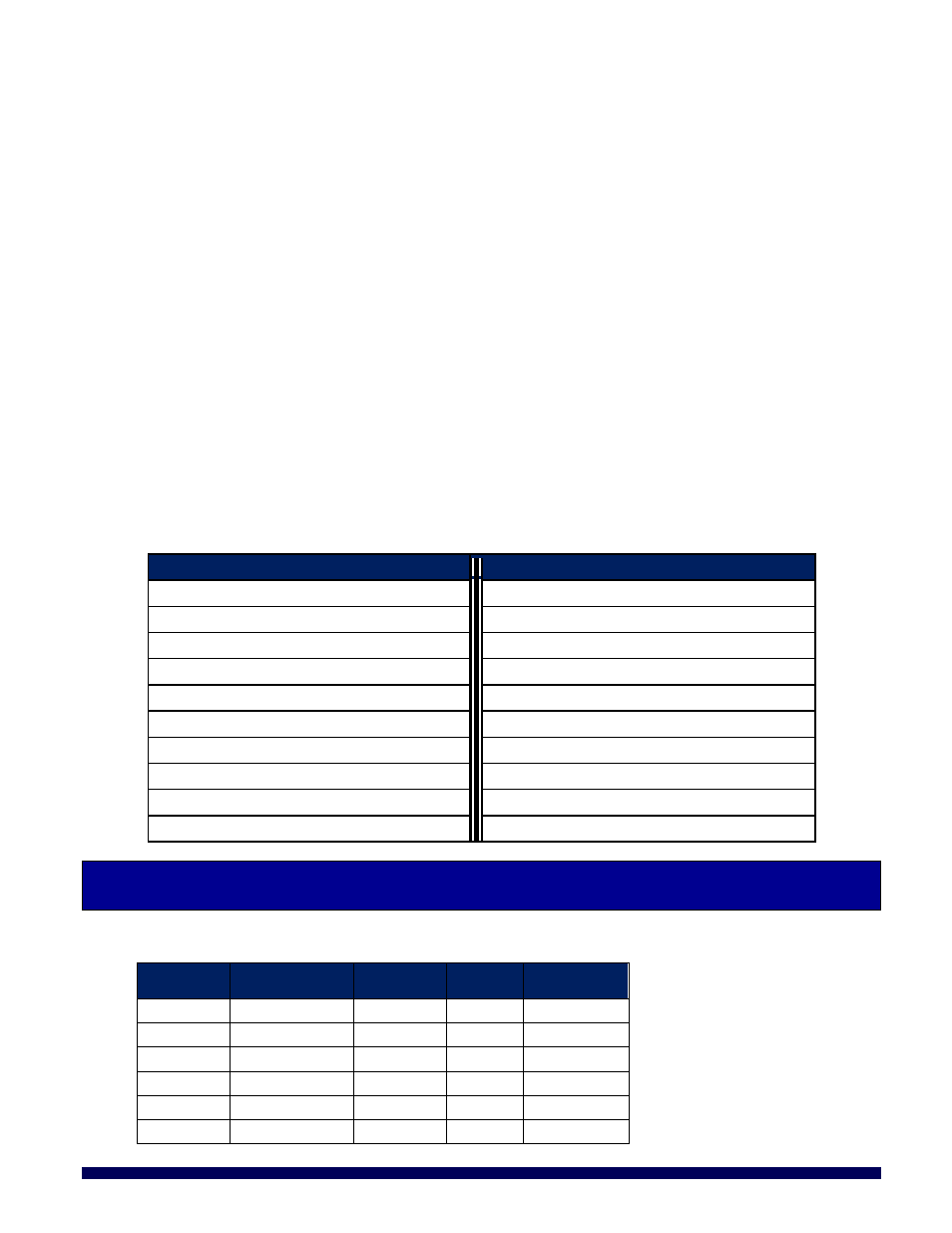
Functional Matrix
MODE
LED
MODE
LED
Night ON + Day OFF
0
Night ON + 10 Hours delay OFF
0.
Night ON + 1 Hour delay OFF
1
Night ON + 11 Hours delay OFF
1.
Night ON + 2 Hours delay OFF
2
Night ON + 12 Hours delay OFF
2.
Night ON + 3 Hours delay OFF
3
Night ON + 13 Hours delay OFF
3.
Night ON + 4 Hours delay OFF
4
Night ON + 14 Hours delay OFF
4.
Night ON + 5 Hours delay OFF
5
Night ON + 15 Hours delay OFF
5.
Night ON + 6 Hours delay OFF
6
Normal Control
6.
Night ON + 7 Hours delay OFF
7
Test (no delay)
7.
Night ON + 8 Hours delay OFF
8
Night ON + 9 Hours delay OFF
9
4 APPLICATION
4.1 W
IRE
G
AUGE
R
EFERENCE
4.1.1
Wire Thickness
AWG
Diameter
inches (mm)
Ohms per
1000ft
Break
Force
Square
mm2
16
0.051 (1.29)
4.016
75 lbs
1.30
14
0.064 (1.63)
2.525
119 lbs
2.08
12
0.081 (2.05)
1.588
197 lbs
3.30
10
0.102 (2.59)
0.999
314 lbs
5.26
8
0.129 (3.26)
0.628
480 lbs
8.30
6
0.162 (4.11)
0.395
760 lbs
13.30
Page 9 of 12
windy
nation
05/06/2014