1 introduction, 1 features, 2 system diagram – Windy Nation Solar Panel Charge Controller User Manual
Page 3: Introduction, Features, System diagram
CHC-1224-xx User Manual
Revision 2.0
1 INTRODUCTION
The WindyNation Solar Panel Charge Controller provides a reliable charging and power management solution for
solar power battery systems with many of the features that you would expect in a much higher priced controller.
This is made possible by the board microprocessor and embedded intelligent software control.
The controller features automatic 12V or 24V DC detect function that will identify the battery voltage upon initial
charge and uses Pulse-Width Modulation (PWM) for automatic charge management and high efficiency. A built in
temperature sensor provides software controlled charge compensation that accurately adjusts the over-discharge
voltage and maximizes your batteries life.
Built in protection includes overload, short circuit, reverse connection, lightning/surge, PV panel reverse current,
over charging, and discharging protection. In the event of a short circuit or overload event, the system will be
protected and remain undamaged.
The enclosure is made of durable plastic with LED lights to provide status indications of charge, battery status,
and system faults as well a user selectable Work Mode/timing interval that will power various DC powered
systems for specified time intervals after dusk such as night/street lighting.
Please read this manual carefully before installing or using the controller and keep it for future reference.
1.1 F
EATURES
Compact size is easy to mount on wall or panel.
Charge controller maintains batteries and extends battery life.
Auto sensing for 12 or 24V systems
Built-in battery test function
Convenient screw terminals for wiring
Separate connections for PV panel, battery, and load
Built-in overload and short circuit protection
Automatic self-recovery after fault removal
LED system status indicators
Requires no adjustments
User selectable on, off, and time modes
Wide operating temperature range -
35˚C to +55˚C (-31˚F to +131˚F)
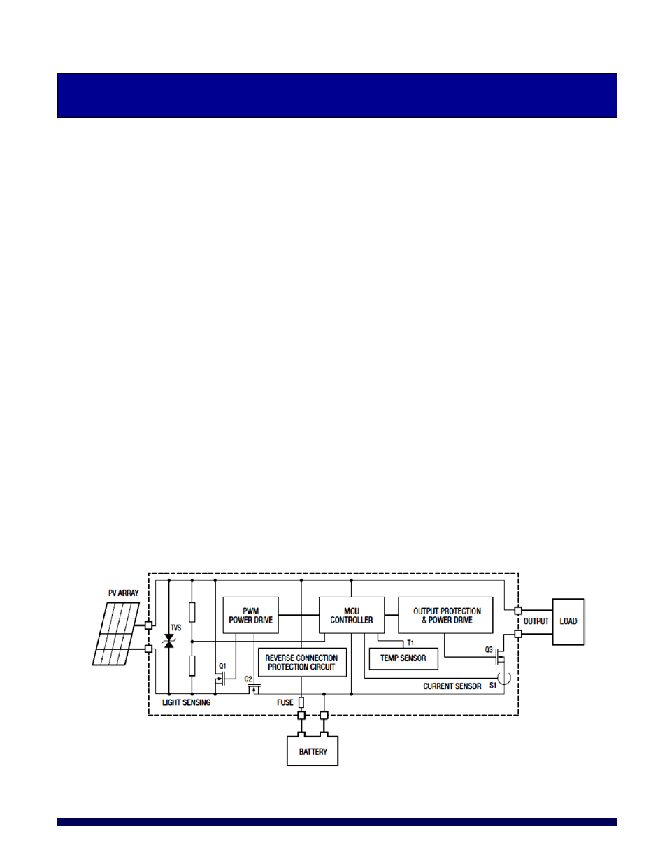
1.2 S
YSTEM
D
IAGRAM
The MCU controller takes sample measurements from the storage battery voltage, discharge current, and
environment temperature to calculate and control the discharge rate.
Page 3 of 12
windy
nation
05/06/2014