Legend, 2 planning and installation, Figure 1: solkit system schematic diagram – STIEBEL ELTRON SOL 25 PLUS User Manual
Page 7: En g l is h
WWW.STIEBEL-ELTRON-USA.COM
SOL 25 PLUS |
7
EN
G
L
IS
H
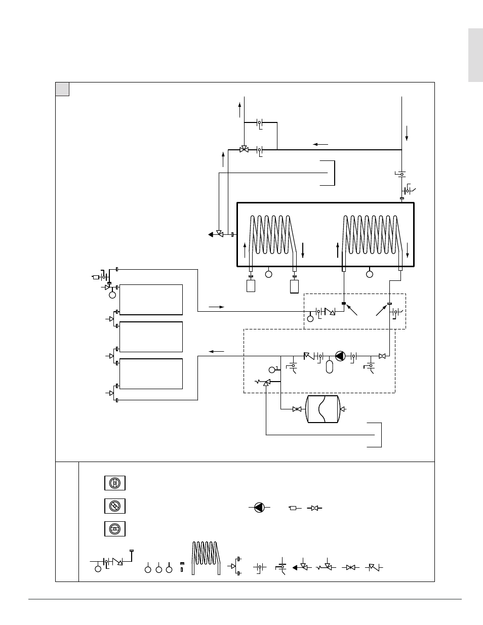
4.2 Planning and Installation
System Schematic
A schematic diagram of components and pipe arrangements for a typical Stiebel Eltron SOLKIT system is shown in Figure 1.
AV
S1
Pipe F
itting
s
SS
MV
Fle
xible
Stainle
ss
St
eel
Tube wit
h
3/4" B
SP
P t
hr
ead union fitting
s
and m
anu
al
ven
t
1" union fitting (S
TAK
)
PT
MV
SS
MV
SS
MV
SS
MV
to field-supplied
supplemen
tal DHW
he
at
er
(tank
le
ss or
tank
-ty
pe)
ov
erflow
con
tainer
1" union fitting (STA
K)
dome
stic
w
at
er
suppl
y
T
BC
1
T
BC
1
TC
S (tank
c
onnection
se
t) - 2 pcs.
Par
t no
. 222418
BC
1
Fill & Dr
ain
Va
lve
Pr
es
sur
e R
el.
Va
lve
P
1" twin nipple
s (2)
BC
1 = b
all
val
ve wit
h
in
teg
rat
ed c
hec
k &
ther
mome
ter
w
ell
Fill & Dr
ain
Va
lve
Pr
es
sur
e
G
aug
e &
Va
lve
50 p
si
ch
eck
va
lve
acti
ve
Two-w
ay
flow acti
ve
va
lve
clo
sed
Pump (3-speed)
Fill & Dr
ain
Va
lve
Thr
ottle and
isol
ation
va
lve
Flow
M
et
er
Pump
Station
Par
t no
. 221339
S
Temper
at
ur
e
Sen
sor
(R
TD)
T
Ther
mome
ter
P
Pr
es
sur
e
ga
ug
e
Ex
pan
sion
Tank
Air
F
ill
Va
lve
45 p
si
†
Di
sc
onnect
Va
lve
Sol
ar
C
ollector
s
Pur
g-O-M
at (a
uto-v
en
t and
an
ti-s
te
aming
val
ve)
HX
2
inle
t
HX
2
outle
t
LEGEND
S2
S3
T/S4
Sol
ar
Stor
ag
e
Tank
Flow
M
et
er
Pump
(3-speed)
Fill & Dr
ain
Va
lve
Ba
ll v
alve
Ch
ec
k V
alve
Di
sc
onnect
Va
lve
Pre
ss
ure
&
Temper
at
ur
e
Rel.
Val
ve
PT
AV
Pre
ss
ure
Rel.
Val
ve
Autom
atic
Ve
nt
Coil-in-
tank
He
at E
xc
hang
er
mi
va
lve
*F
or
mor
e
in
for
m
ation on t
he pump s
tation and s
tor
ag
e tank
, ple
ase r
ef
er
to “S
BB
Stor
ag
e
Tank
s f
or
Sol
ar
A
pplic
ation
s”
in
stall
ation m
anu
al.
†
Pr
e-c
har
ged pr
es
sur
e, me
asur
ed
when open to at
mo
spher
e.
Figure 1: SOLKIT System Schematic Diagram
1