2 vertical 45° mounting on a wall – STIEBEL ELTRON SOL 25 PLUS User Manual
Page 14
14
| SOL 25 PLUS
WWW.STIEBEL-ELTRON-USA.COM
5.2.1 Vertical 45° Mounting on a Flat Roof
(Please review section 5.2.0)
1. Choose attachment site, allowing for subsequent pipe
penetration.
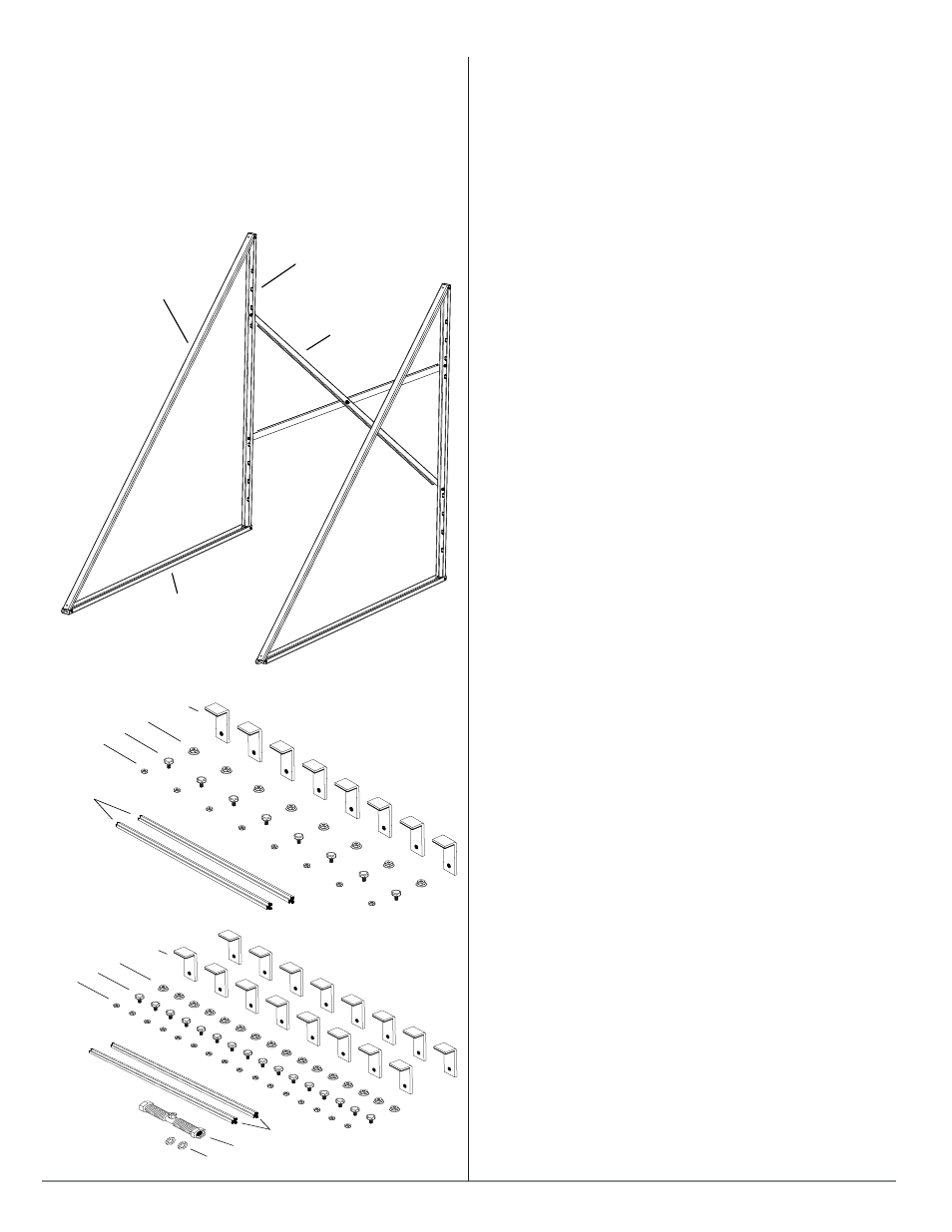
2. Assemble 2 triangular trusses using the 65” rails (M-103), the 92”
rails (M-102), the brackets (M-101), and the 55 mm bolts as shown
in Figure 5.2.1.
Support Riser
Support Base
Support Diagonal
Brace
Figure 5.2.3: Assembled triangle trusses with cross-braces.
3. Bolt the trusses to the cross braces connecting the bolts as shown
in Figure 5.2.2. The resulting assembly should look similar to Figure
5.2.3. The collector frames may then be bolted to the holes in the
92” rails using the 20 mm bolts. The collector frames, as well as the
number of trusses used, depends upon the number of collectors
being installed (see Table 5.1). If multiple flat-roof mounting frames
are being set up next to one another, use frame connector kits
(SFC001, shown in Figure 5.2.6) to join them, as shown in Figures
5.2.7 and 5.2.8.
4. If installing one collector, the triangular trusses with cross braces
must be set up at intervals of ≤ 43 in. (110 cm), If installing two or
more collectors, the triangle trusses with their attached cross braces
are to be positioned at the midpoint, behind the collectors. With a 3
collector system the 3 triangular trusses should be equidistant with
2 sets of cross braces interconnecting them. The resulting assembly
should then be centered to support the R1/R2/SFC001 frame
assembly.
5. When installing four or five trusses, brace both end spans with
crossbraces, as shown in 5.2.8. For six or more trusses, cross-braces
should also be placed in an inside span.
6. Fasten the flat-roof mounting racks to the roof in an appropriate
manner, or weight them down with at least 400 lbs. (180 kg) of
solid, dead weight (e.g. concrete slab) per collector if the installed
height is less than 25 ft (8 m). Remember to take the static and
dynamic (e.g., wind) loading into account for the roof structure.
7. For installed heights above 25 ft. (8 m), weighting is not
advisable due to the higher wind loading conditions. In this case,
the holes in the 65” rail at the base (M-103) should be used to fasten
the mounting hardware to the roof (six M6 bolts per horizontal
support).
5.2.2 Vertical 45° Mounting on a Wall
Procedures described above for mounting of collectors upon a flat
roof apply to wall mounting, except for the following:
1. Cross braces should be attached to the 65” rail at the base of the
trusses rather than the ones at the rear.
2. Fasten the rear 65” rail of the trusses to the wall using the
mounting holes in a suitible manner.
3. Low elevation mounting configurations may be prone to damage
from falling ice or nearby vehicles or other hazards. Appropriate
precautions should be taken to mitigate these hazards.
M10 nuts
M10 bolts
M6 nuts
Profile rails
Anchor brackets (panel clips)
Compensator
(Flexible Stainless Steel Pipe)
Seals
Figure 5.2.5: R2 Mounting Frame for Vertical Collector Arrangement
M10 nuts
M10 bolts
M6 nuts
Profile rails
Anchor brackets (panel clips)
Figure 5.2.4: R1 Mounting Frame for Vertical Collector Arrangement