Steffes HPB22 Owners Manual User Manual
Page 15
- Page 12 -
G.
FINAL TEST PROCEDURE
TEST EQUIPMENT NEEDED:
1.
Digital Volt-Ohm meter.
2.
Clamp-on Amp meter.
1.
Check all electrical connections for proper termination placement, and
that they have been tightened properly.
2.
Energize electrical circuits.
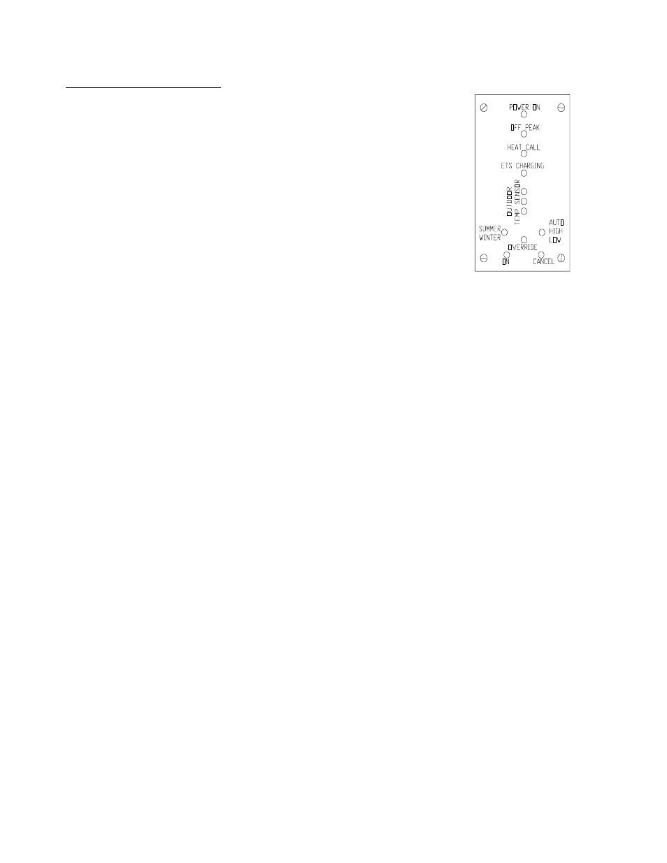
(See Figure 9 for switch positions on steps 3, 4, and 5)
3.
In the off-peak mode and with the outdoor air sensor disconnected,
jumper sensor connection terminals "W" & "R" of the charge control
circuit board together and perform the following tests:
A.
Set selector switches to SUMMER and AUTO positions. One outdoor sensor light should be on. Next,
check unit's charging circuit amperages. On 240V systems, this should read:
HPB11B =30.5 Amp
HPB15B =30.5 Amp
HPB22B =46 Amp
B.
Set selector switches to WINTER and AUTO positions. Two outdoor sensor lights should be on, and
unit amperage on 240V systems should read:
HPB11B = 46 Amp
HPB15B =61 Amp
HPB22B = 91.5 Amp
C.
Set selector switches to WINTER and HIGH position. Three outdoor sensor lights should be on, and
unit amperage on 240V systems should read:
HPB11B = 46 Amp
HPB15B =61 Amp
HPB22B =91.5 Amp
Simulate an on-peak period by changing the status of the blue and blue/white wires. All heating
elements should cycle off.
4.
With unit in the on-peak mode, depress the override "START" switch; and, observe the indicator light. Light
should be illuminated.
(NOTE:
This step may be ignored if the on-peak override feature is not authorized by the electrical
utility.)
5.
Remove outdoor sensor jumpers and reconnect outdoor air temperature sensor. Set selector switches to
"AUTO" and "WINTER" positions.
6.
With unit in the off-peak mode, initiate a Stage 2 heat call or jumper from "R" to "W" on the boosters
interface board. The unit's blower should energize and damper motor should drive in a CCW direction. This
movement is quite slow. (90
o
F takes about three minutes.)
7.
Stop the heat call. Watch for the blower to de-energize and the damper motor to return to it's clockwise
position.
8.
Replace electrical box cover and check for proper electrical panel circuit labeling.
9.
Present owners manual and warranty card to owner.
CHARGE CONTROL
CIRCUIT BOARD PANEL
(FIGURE 9)