Installation – Steffes HPB22 Owners Manual User Manual
Page 10
- Page 7 -
3. INSTALLATION
A. SHIPPING
Steffes ETS Heat Pump Boosters are shipped in modular fashion for ease of handling. (See Shipping Data Sheet in
Appendix). Following delivery of the booster to its installation site, merely remove the packaging materials; and, the
unit is ready for installation.
B. UNIT PLACEMENT
The weight of the unit must be taken into consideration when selecting the installation surface. A level concrete
floor is the best surface on which to place the Heat Pump Booster, but most well supported surfaces are acceptable.
CAUTION: Consult a building contractor or architect if in doubt about floor load capacity.
See unit specifications in the Appendix for size and weight of unit being installed.
Locating the Heat Pump Booster directly adjacent to the home's heat pump is most desirable, but any suitable
location within twenty (20) feet of the heat pump's warm air plenum is acceptable. Consult factory on locations of
greater distances.
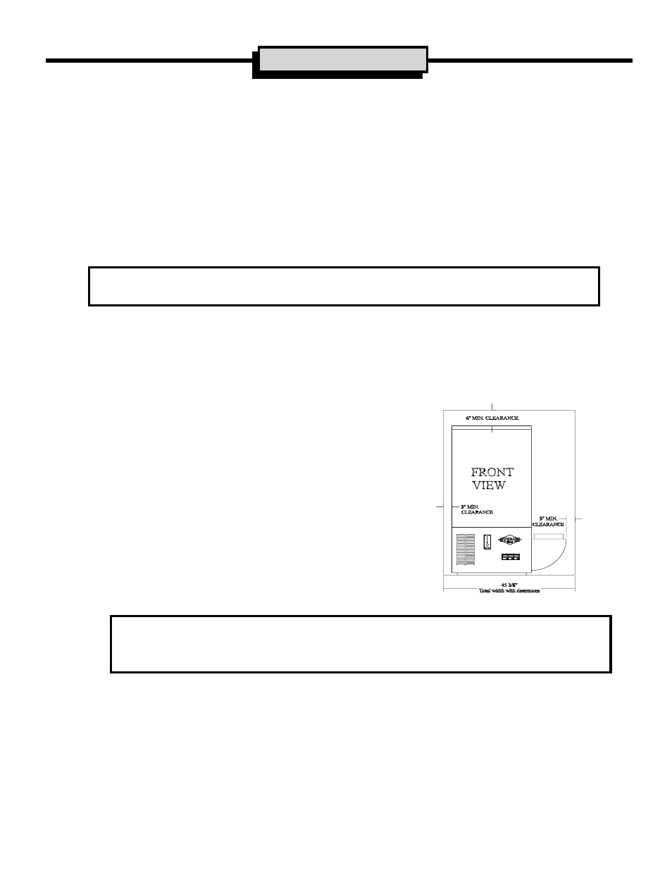
C. CLEARANCE REQUIREMENTS
Allow clearance of three (3) inches from back and sides, six (6)
inches top clearance, and a minimum of thirty-six (36) inches from the
front of the unit to allow for servicing. This clearance area must be
kept open and free of debris. Do not place anything on top of unit or
allow objects to fall between the booster and adjoining walls. A
minimum of one (1) inch and zero (0) inches to a combustible floor
surface must be maintained between the duct and the booster.
Small enclosed areas where units are to be installed must be well
ventilated. A minimum of sixty-four (64) square feet is required with
a minimum 24" X 24" door louvre.
D. SET-UP AND BRICK LOADING PROCEDURE
GENERAL NOTES:
A.
See Shipping Data Sheet in Appendix for components included with unit in shipment.
B.
For cross reference to number coded components, see Figure 10.
INSTALLATION TIPS:
a. Remove loose brick materials during loading phase to prevent uneven stacking
of bricks.
b. See Figure 4 for installation of the last middle brick.
c. To ensure adequate room for brickloading, the top or bottom 1' X 4' core spacer piece
can be used to hold the inner brick cavity wells apart.
CLEARANCE DIAGRAM
(FIGURE 3)