Steffes HPB22 Owners Manual User Manual
Page 13
- Page 10 -
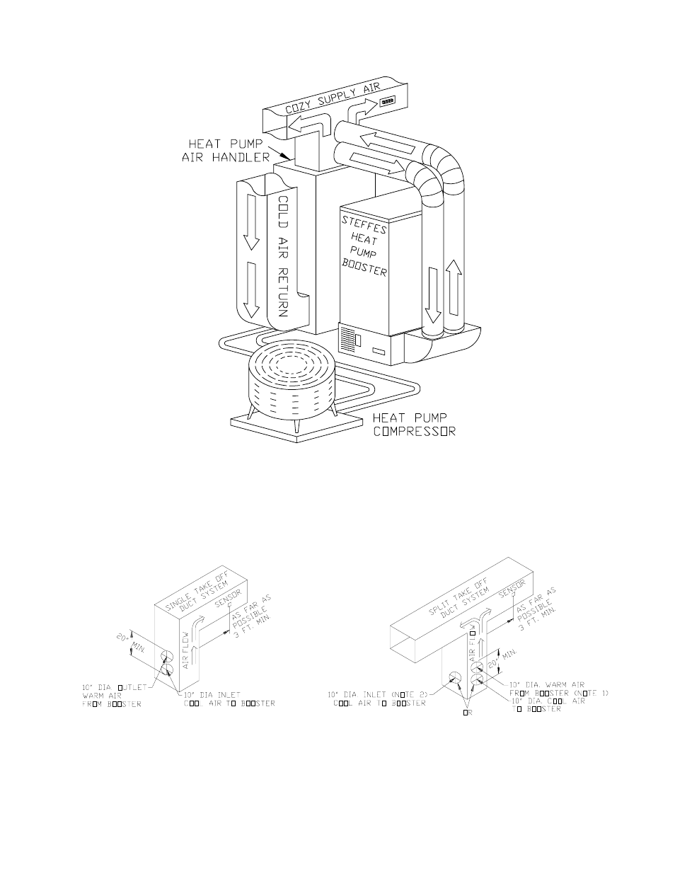
MECHANICAL CONNECTION OVERVIEW
(FIGURE 6)
NOTES:
1.
Both inlet and outlets of the HPB unit must be connected to the supply side of the duct system.
2.
With a split take off duct system the warm air duct from the booster must be placed to ensure
even discharge of heat to both sides of the duct system. (Warm air duct from HPB should be
centered on the plenum.)
TYPICAL BOOSTER
MECHANICAL CONNECTIONS
(FIGURE 7)
This manual is related to the following products: