DVR systems DVRxx04HF-S Series User Manual
Page 59
49
485 A/B
485 communication port. They are used to control devices such as
PTZ. Please parallel connect 120TΩ between A/B cables if there are
too many PTZ decoders.
3.8.1.2 1.5U Series (Simple 1.5U)
The 1.5U series product interface is shown as in Figure 3-3.
Figure 3-3
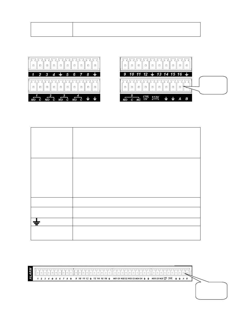
You can refer to the following sheet and Figure 3-3 for alarm input and output information.
In the first line, from
the left to the right,:
1,2,3,4,5,
6,7,8,9,10,
11,12,13,14,
15,16
ALARM 1 to ALARM 16. The alarm becomes active in low voltage.
In the second line,
from the left to the
right:
NO1 C1,
NO2 C2,
NO3 C3,
NO4 C4,
NO5 C5 NC5
The first four are four groups of normal open activation output
(on/off button)
NO5 C5 NC5 is a group of NO/NC activation output (on/off button)
CTRL 12V
Control power output. You need to close the device power to cancel
the alarm.
+12V
It is external power input. Need the peripheral equipment to provide
+12V power (below 1A).
Earth cable.
485 A/B
485 communication port. They are used to control devices such as
PTZ. Please parallel connect 120TΩ between A/B cables if there are
too many PTZ decoders.
3.8.1.3 2U Series
The 2U series product interface is shown as in
Figure
3-4
.
Figure 3-4
You can refer to the following sheet and
AB cable
connection
AB cable
connection