Chapter 2 - set-up and installation, Installing the n525, Chapter 2 set-up and installation – CANOGA PERKINS N525 Ethernet Termination Service Unit User Manual
Page 11
N525 Ethernet Termination Service Unit
2-1
Chapter 2
Set-up and Installation
This section describes how to set up and install the N525 and its interface modules.
Before setting up the N525, make sure a 9 pin RS-232 cable is available (required to
connect the N525’s Management Port to a VT100 type terminal or PC for setup and
configuration).
Installing the N525
The N525 is tested and inspected before shipment from the factory. If there is obvious
damage to the shipping container, contact the carrier immediately.
Caution: Follow electrostatic discharge (ESD) safety precautions when handling
Canoga Perkins products, as with all electronic devices with static
sensitive components.
1. Unpack the N525. Keep the shipping container until the unit is installed and fully
operational. In the unlikely event that the unit is defective, contact Canoga Perkins
Customer Service for a Return Authorization Number (RMA) and instructions for return
shipment. Additional Warranty and Product Return information is in Appendix A.
2. The N525 can be rack mounted, wall mounted, or placed on a shelf or any other flat
surface.
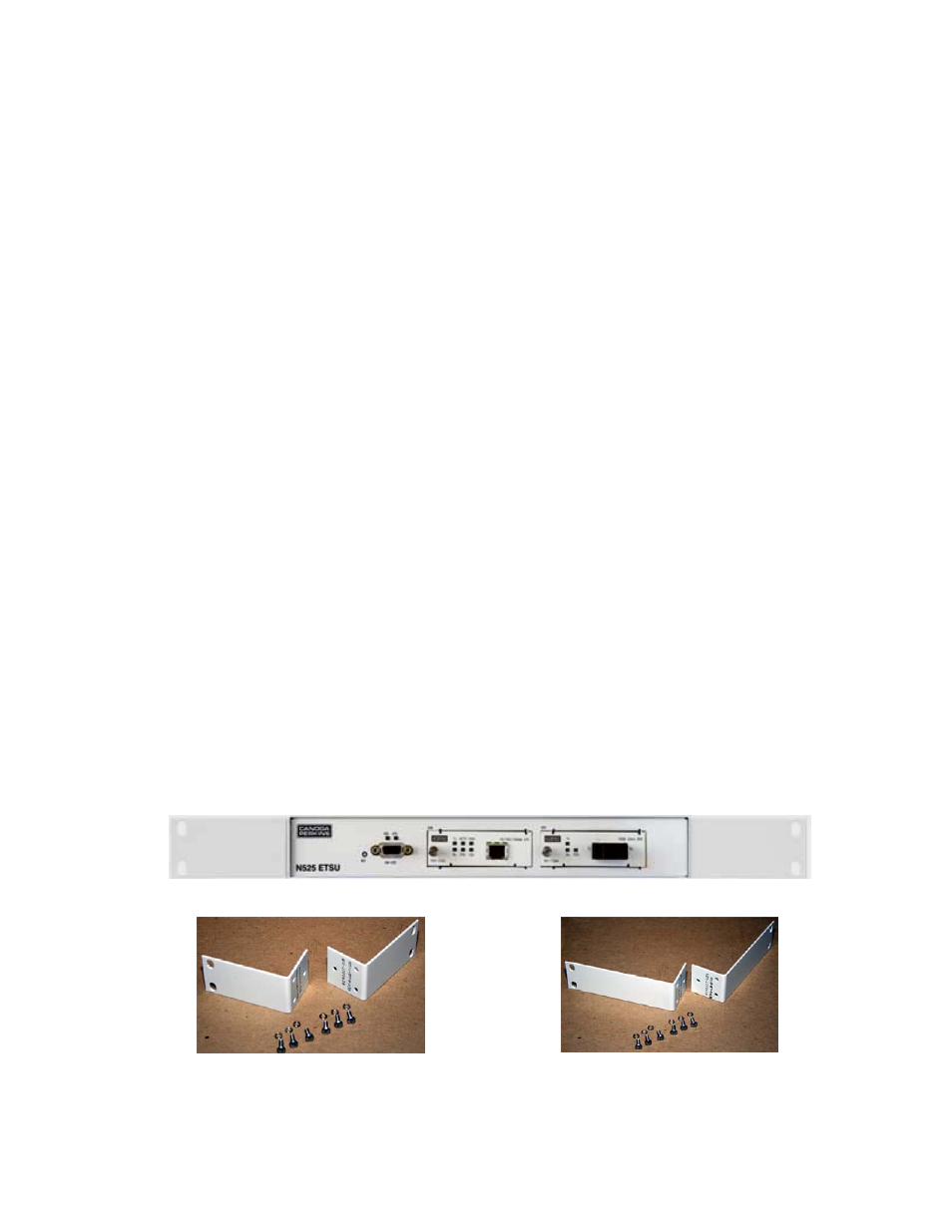
a. Rack Mounting: To rack mount the N525, attach Rack Mount Kit 1802-2008 for
19” racks, or Rack Mount Kit 1802-2009 for 23” racks. The Rack Mount Kits
includes mounting brackets and screws to attach the brackets to the N525. The
brackets attach to the three threaded holes on the side of the N525 toward the
front. Be sure to place the Lock Washer between the Screw Head and Bracket
as shown figure 5.
Figure 2 – N525 with 19” Rack Mount Brackets
Figure 3 – 19” Rack Mount Kit
Figure 4 – 23” Rack Mount Kit