10 switch and jumper settings, 11 mean time between failures (mtbf), 10 switch and jumper setting – CANOGA PERKINS 2270 Fiber Optic Modem User Manual
Page 13: 2 locations of various switches, 1 0 switch and jumper settings, 1 1 mean time between failures (mtbf)
13
2270 Fiber Optic Modem
These settings give minimum and maximum losses for each of the four possible switch combina-
tions. There is overlap between these ranges that is guaranteed to meet or exceed
+/−
1.0 dB from
the transition points.
The performance of every modem is guaranteed to fit the parameters given above. Some modems
may significantly exceed these performance limits, but reliable operation and unit interchangeabil-
ity is not guaranteed outside of these limits.
1.1
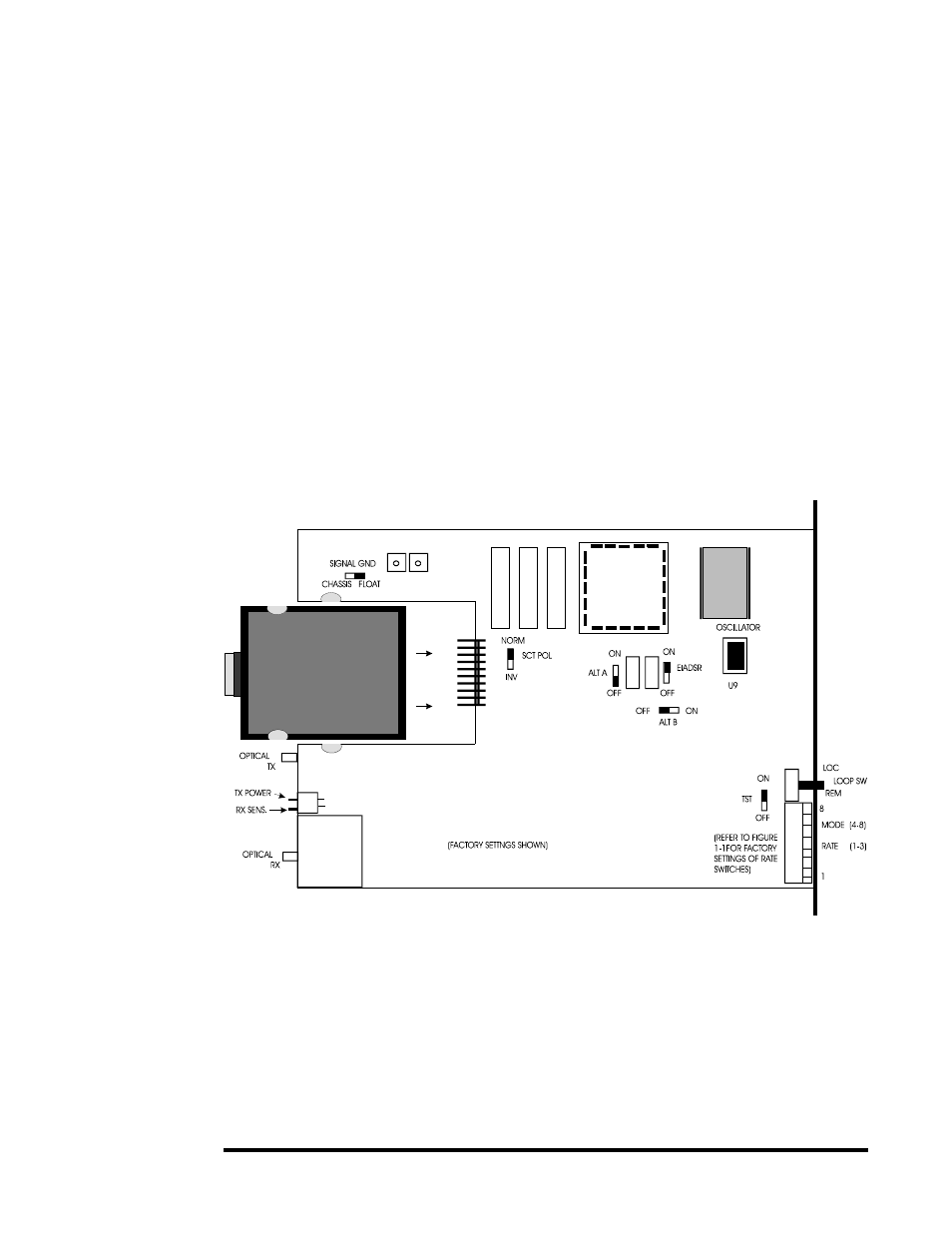
0 Switch and Jumper Settings
See Figure 1-2 for the location of specific switches and jumpers. Tables 1-C and 1-D summarize
the functions of the 2270's switches and jumpers.
1.1
1 Mean Time Between Failures (MTBF)
The 2270's Mean Time Between Failures (MTBF) figure, 62,500 hours (calculated), has been
determined from calculations that are similar to MIL-217E. It assumes a Ground Benign environ-
ment and excludes failures which are not service-affecting. This MTBF figure is for a Rack-Mount
2270 with a MIL-STD 188-114C interface (Model 2270-R-TW8-11-08-0).
Figure 1-2.
Locations of
Various Switches