Drive component maintenance – Beckett ADC 24Vdc User Manual
Page 9
9
24 Vdc ADC Burner Manual
Section: Drive Component Maintenance
Drive Component
Maintenance
A. Motor, Blower Wheel, and Coupling
Replacement
The motor will require replacement if the proper voltage is
measured at the motor input, and the motor will either not
run, or the current draw with a free running pump exceeds
10% of the rated current.
To replace the burner motor, coupling and/or blower wheel
perform the following steps.
1. Before servicing, turn off and/or disconnect all power
to the burner.
2. Disconnect the burner motor wires.
3. Remove the bolts securing the motor to the burner
housing.
4. Remove the motor, coupling, and blower wheel.
5. Loosen the set screw on the blower wheel to slide
the existing wheel off the shaft.
6. Slide the new blower wheel onto the old shaft (after
thoroughly cleaning housing) and/or slide the old
blower wheel onto the new motor shaft.
7. Place a .030” (1/32” ± 1/64”) feeler gauge between
the blower wheel and the motor housing.
8. Slide the blower wheel toward the motor until it
contacts the feeler gauge.
9. Rotate the blower wheel until the setscrew is centered
on the fl at of the motor shaft. Tighten the setscrew to
secure the wheel.
10. Slide the motor coupling on the motor shaft, then
install the motor on the burner housing. Ensure that
the motor coupling fi ts between the motor shaft and
the pump shaft inside the housing. Tighten the motor
retaining screws. Reconnect the wires.
11.
Restore power, start the burner and perform
the combustion test described previously in this
manual.
B. Pump Maintenance
General Pump Information
Important information - Long or oversized inlet lines may
require the pump to operate dry during initial bleeding
period. In such cases, the priming may be assisted
by injecting fuel oil in the pump gear set. Under lift
conditions, lines and fi ttings must be air tight. To assure
this, “Pipe Dope” may be applied to both the used and
unused inlet and return fi ttings. Do NOT use Tefl on tape
or compression fi ttings
Mounting Position - Beckett CleanCut pump may be
mounted in any position (except upside-down in a single
pipe installation).
Vacuum Check - A Vacuum Gauge may be installed in
either of the 1/4” NPT inlet ports.
Pressure Check- When a pressure check is made, use
the nozzle port. If the bleed port is used, the reading on
the gauge should be approximately 5 psig higher than the
pressure reading on the nozzle port. See Figure 8.
Cutoff Check - To check cutoff pressure dead head a
pressure gauge in the nozzle port. Run the burner for a
short period of time. Shut the burner off. The pressure
will drop and hold above zero. Pressurized or gravity feed
installations must not exceed 3 psig on inlet line or return
line at the pump per NFPA 31. A pressure greater than 10
psig may cause damage to the shaft seal.
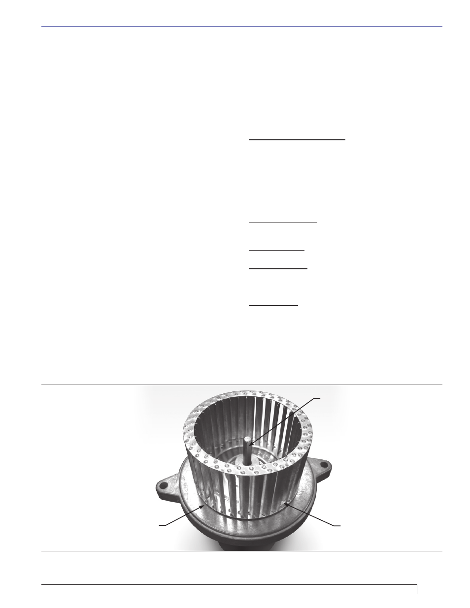
Figure 7. – Blower Wheel
Insert feeler gauge between
blower and motor
Flat face on motor shaft
Access hole to set screw