D. servicing nozzle line assembly, E. check/adjust “z” dimension, Ab c – Beckett ADC 24Vdc User Manual
Page 6
6
Section: Nozzle Assembly Maintenance
Item #
Description
1
Electrode Contact (3” ATC or extension over 3”)
2
Nozzle Line
3
Spider spacer assembly
4
Static Plate
5
Electrode clamp
6
Electrode clamp retaining screws
Item #
Description
7
Nozzle line setscrew
8
Electrode Insulator
9
Nozzle adapter
10
Nozzle tip
11
Electrode tip
The igniter must be grounded to the burner before
checking the following. To check the igniter, ensure all
power to the burner is off and use an ohmmeter to check
the resistance between the two springs. The meter should
read between 480 - 580 ohms.
The igniter should be replaced if the meter indicates an
open circuit, or the spring-to-spring resistance exceeds
the 480 - 580 ohms range by more than 10%..
D. Servicing Nozzle Line Assembly
Before proceeding, turn off power to the burner.
1. Disconnect the oil connector tube from the nozzle
line.
2. Referring to Figure 3, loosen the two screws securing
the igniter retaining clips (a) and rotate both clips to
release the igniter baseplate. Then tilt the igniter
back on its hinge.
3. Remove the splined nut (b).
4. Remove the nozzle line assembly from the burner,
being careful not to damage the electrodes or
insulators while handling. To ease removal of short
assemblies, it may be necessary to loosen the
escutcheon plate (c). Reset to the edge of the label.
5. To replace the nozzle line assembly, reverse the
above steps.
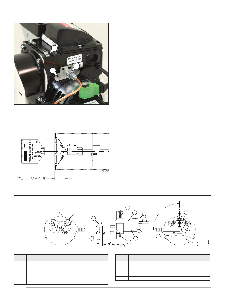
E. Check/Adjust “Z” Dimension
Refer to Figure 4. The critical “Z” dimension is the
distance from the face of the nozzle to the fl at face of
the head. This distance for F heads is 1-1/8”. The “Z”
dimension is factory set for burners shipped with the air
Figure 4. ‘Z’ Dimensions Using Gauge
Figure 5. Nozzle, Line & Electrode Assembly
10
11
6
8
1
2
7
4
9
3
5
4
90°
Contacts to be parallel with
horizontal center line within 2°.
Electrode gap to be centered
with nozzle center.
Figure 3. Igniter Hinge & Retainer Clips
a
b
c