Installation instructions, Figure 3 interconnect wiring diagram – Kidde i12010SCO User Manual
Page 14
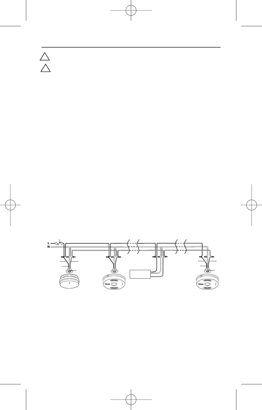
WIRING INSTRUCTIONS FOR AC QUICK CONNECT HARNESS
CAUTION! TURN OFF THE MAIN POWER TO THE
CIRCUIT BEFORE WIRING THE ALARM.
• For alarms that are used as single station, DO NOT CONNECT
THE RED WIRE TO ANYTHING. Leave the red wire insulating
cap in place to make certain that the red wire cannot contact
any metal parts or the electrical box.
• When alarms are interconnected, all interconnected units must
be powered from a single circuit.
• A maximum of 24 Kidde Safety devices may be interconnected
in a multiple station arrangement. The interconnect system
should not exceed the NFPA interconnect limit of 12 smoke
alarms and/or 18 alarms total (smoke, CO, Smoke/ CO
Combination, heat, etc.). This Smoke/CO combination alarm
must be counted as a smoke alarm when determining the
number of units on an interconnect line. With 18 alarms
interconnected, it is still possible to interconnect up to a total
of 6 remote signaling devices and /or relay modules (see page
15 for details on interconnecting Kidde devices).
• The maximum wire run distance between the first and last unit
in an interconnected system is 1000 feet.
Installation Instructions
12
FUSE OR CIRCUIT BREAKER
RED
BLACK
WHITE
CONNECTOR
RED
BLACK
WHITE
CONNECTOR
First
Alarm
Additional
Alarm
Kidde Relay Module
SM120X, CO120X
or both
Additional
Alarm
Optional
Accessory
WIRES ON ALARM HARNESS
CONNECTED TO
Black
Hot Side of AC Line
White
Neutral Side of AC Line
Red
Interconnect Lines (Red Wires) of
Other Units in the Multiple Station
Set up
FIGURE 3 Interconnect Wiring Diagram
!
!
2550-7201-01(i12010SCO)_V4.qxd:_ 2014.2.20 10:24 AM Page 14