Step 3: putting it all together – Vernier CBL Made Easy User Manual
Page 15
CBL Made Easy!
11
Step 3: Putting it All Together
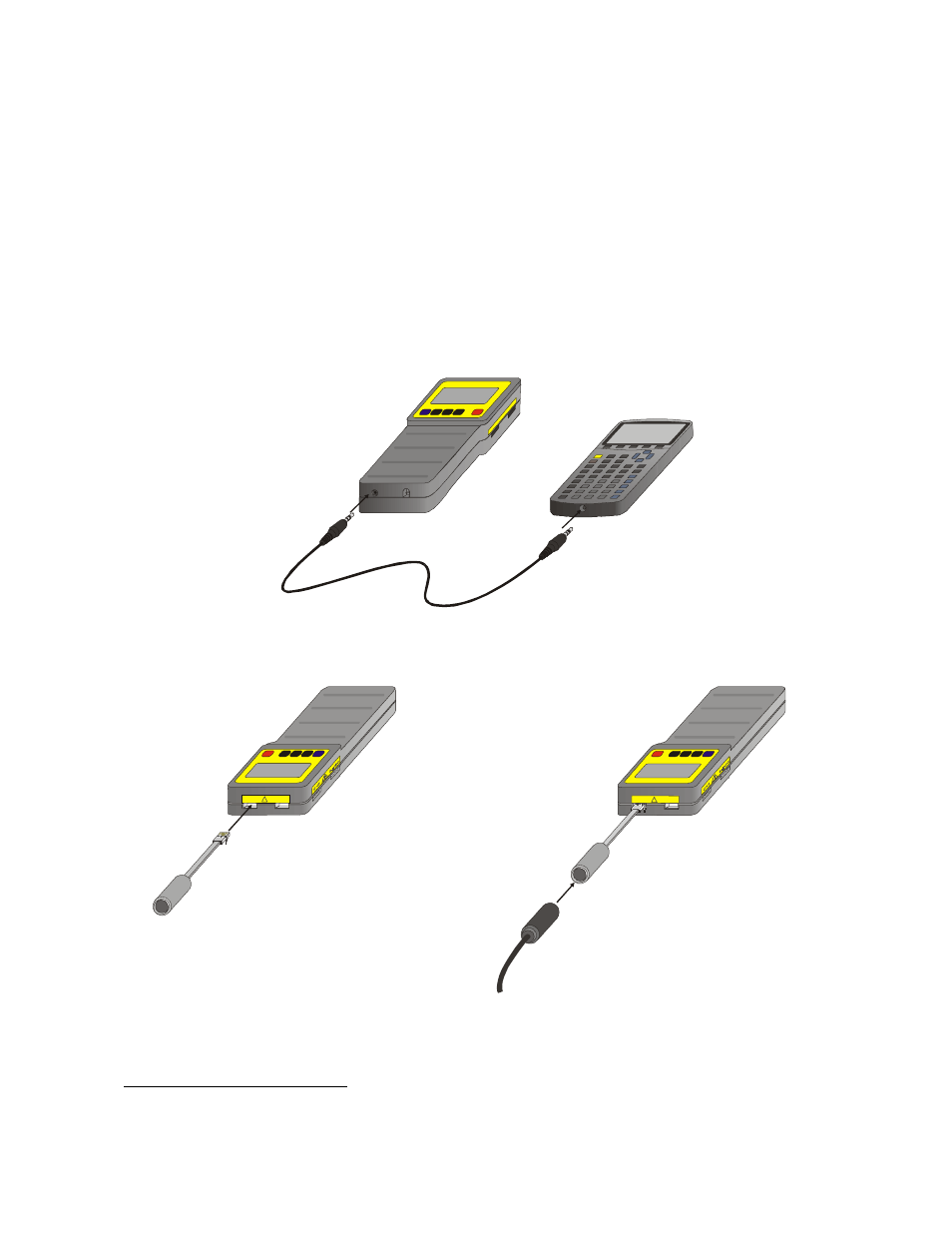
Now you are ready to get your hardware set up. This is the easy part. At the base of the CBL are two ports.
The left port is the communications port. This connects the CBL to the calculator via the black calculator
link cable. Be sure to push the cables firmly in when connecting the two components.
3
There are four jacks located along the top and the left of the CBL unit in which you can plug Vernier or TI
probes. They are labeled CH1, CH2, CH3, and Sonic. You should use the lowest channel available. The
Sonic port is used only for the Motion Detector. If the order code for Vernier sensors ends with the
extension “-DIN,” (a 5-pin round plug) then it requires a DIN-BTA adapter. For more information about
adapters, refer to Appendix B.
Ste p 1: P lug th e bla ck lin k c ab le into th e link p ort on th e
b o ttom o f the C B L a nd T I gra p h in g ca lcu la tor.
C H1
C H2
!
S tep 2: P lug th e C BL -D IN
a d a p te r into C h a n n el 1
o f th e C B L .
C H1
C H2
!
Step 3: C onn ec t the sensor to the
C B L-D IN adapter.
3
The right port allows you to connect an AC adapter (order code IPS). This will prolong battery life when doing
experiments indoors.