Assembly of the brake linkage step 1 step 3 step 2, Assembly of the engine onto chassis – OFNA Racing LD3 Pro User Manual
Page 24
ASSEMBLY OF THROTTLE HORN INTO SERVO AND BRAKE LEVER
M2x12mm
Screw
2mm
Plastics Washer
Servo Horn
10769
Sevro Horn
Adapter
ASSEMBLY OF THE BRAKE LINKAGE
Step 1
Step 3
Step 2
30530
Throttle
Ball End
10300
Alum.
Stopper
10300
Alum.
Stopper
10300Alum.
Stopper
3x3mm
Set Screw
3x3mm
Set Screw
3x3mm
Set Screw
94033
3x3mm
Set Screw
THROTTLE
SERVO
Brake Lever
Screw
3x3mm
Set Screw
2mm
Rod
Throttle
Slider
Throttle
Rod
*Use the screw provided from your servo.
36130
30171
38180
10768
38274
Throttle
Spring
* Align the throttle servo horn in 90 degree.
* Take the 2mm plastic washer from
the shocks plastic tree.
* Attach the throttle ball end onto
the throttle ball on the carburetor
( For slide carburetor. )
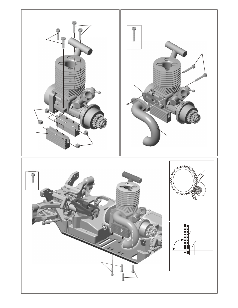
ASSEMBLY OF THE ENGINE ONTO CHASSIS
M3x10mm
Screw
94003
M3x10mm
Screw
94003
M3x10mm
Screw
38150
M3
Nylon Nut
38150
M3
Nylon Nut
94007
M3x20mm
Cap Screw
94007
M3x20mm
Cap Screw
38150
M3x12mm
Hex Screw
38150
M3x12mm
Hex Screw
ASSEMBLY OF THE ENGINE
ONTO ENGINE MOUNT
ASSEMBLY OF THE MANIFOLD
Manifold Gasket
38286
Side Exhaust
Manifold
*Put the nylon nut
into the groove of the
engine mount.
38150
Engine Mount
38162
* Use the note book paper to set gear backlash
between Spur Gear and Clutch Bell Gear.
* If the space is not correct, the spur gear will
be damaged.
Note book Paper.
* Loose or tighten 3x12mm cap screw
to align spur gear and clutch bell gear
to 90 degree.
2 Speed
Spur Gear
2 Speed Bell
90 Degree