Rane RPE 228d User Manual
Page 2
Manual-2
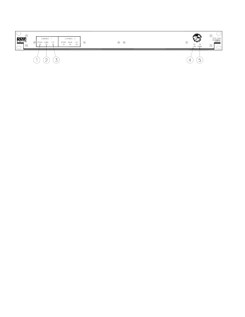
FRONT PANEL DESCRIPTION
ቢ BYPASS (red) lights whenever the audio relay Bypass for the Channel is active. This occurs for a few seconds after power-
up, or when BYPASS is selected in RaneWare.
ባ SIGNAL (green) indicates the presence of a significant analog audio signal on the Input to the Channel (typically -27 dBu).
ቤ CLIP (red) flashes when an audio level for the Channel in the unit approaches digital clipping level (typically 3 dB below
clipping).
ብ COM (yellow, communications) flashes when a message for the unit is received from a PC compatible computer. There is a
brief flash when using the Memory Recall Port.
ቦ POWER indicates that the unit is happily connected to a powered remote supply.
RPE 228d CONNECTION
When first connecting the RPE 228d to other components
in your system, leave the power supply for last. This will give
you a chance to correct any mistakes before any damage is
done to your speakers, ears, etc.
The RPE 228d requires a Rane RS 1 (provided with each
unit) or compatible power supply. There are #6-32 screws
provided for chassis ground. Connect a wire from this point to
a known earth ground, such as an amplifier chassis. This may
not be necessary when installed in a rack with other grounded
units.
The RPE 228d will operate at moderately high ambient
temperatures. Large racks of equipment may generate excess
heat, requiring extra space beween units, and/or forced air
ventilation to reduce the ambient temperature in the rack.
The RPE 228d has balanced Inputs and Outputs, with
chassis-grounded shields. This chassis ground is not signal
ground, although the two grounds are connected internally.
The chassis ground is intended to be connected to an earth
ground. The RPE 228d is intended to be connected to other
balanced equipment with chassis-grounded shields. Connect
the non-inverting audio lines to the ‘+’ terminals, and the
inverting lines to the ‘–’ terminals. Connect the cable shields
to the ground terminal on the Euroblock or screws. Connect
shields at both ends of the cables.
To control the units from a computer, use nine-pin RS-232
cables which are 50 feet or shorter. The cable must not be a
null-modem type. A short cable is supplied for connecting
adjacent units. Daisy-chain up to 16 units at a time by
connecting the COM port on the computer to the INPUT
connector on the first unit, and the OUTPUT connector of
each unit to the next unit’s INPUT.
The DEVICE ADDRESS switch identifies each unit with
an ‘address’, and must be set uniquely for each unit. The
switches form a binary code from 0 through 255. Only the
numbers 1-250 may be used. The place values of each switch
are marked on the rear panel. To set a specific address, refer
to the “Setting the Device Address” section.