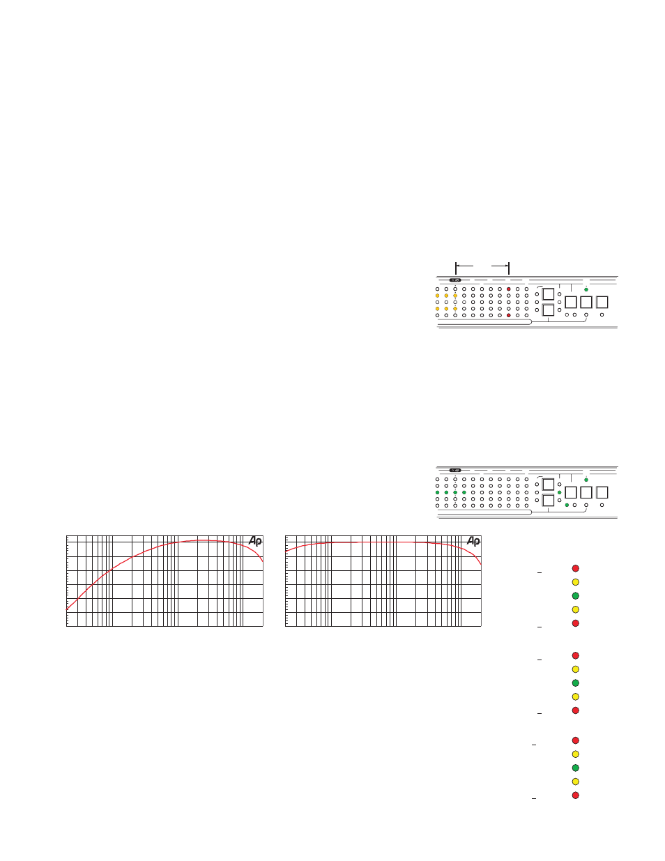
Manual- step by step instructions, Spl mode a-weighting curve, Spl mode c-weighting curve – Rane RA 30 User Manual
Page 6: 1 db, 3 db, 6 db, Rta scales
Manual-
Step by Step Instructions
I. Stereo VU Meter
A. Connect program source to the LINE INPUTS on the rear. If mono operation is desired, connect the mono program
source to the LEFT INPUT.
B. Set the SOURCE switch to LINE IN.
C. Set the GAIN control to the center detent to calibrate the 0 dB mark on the VU scale to +4 dBu.
OR
Set the GAIN control fully clockwise to calibrate the 0 dB mark on the VU scale to -10 dBV.
D. Select the METER mode by pressing the METER/RTA button so the METER LED illuminates.
E. Read the VU level from the display using the VU scale (top row, -30 to +12).
1. The two horizontal yellow rows indicate the VU level. The top row displays the Left Input. The bottom row displays
the Right Input. Levels above +3 dB on the VU scale switch to the red rows.
2. If only the LEFT INPUT is connected, the RIGHT INPUT is internally connected for Mono operation. This
results in the Left and Right displays tracking each other.
3. The VU meter incorporates an instantaneous peak hold function with a 2 second hold time. The peak value is dis-
played with a single LED for each channel (transient peaks can often be 6 to 20 dB above the rms average value).
If the held peak value is greater than +12 dB on the VU scale, the
+12 dB LEDs stay illuminated. In this case, the Input gain can be de-
creased until the peak value is not “stuck” at +12 dB. For a calibrated
peak measurement, the input gain can be set to minimum which sets
the 0 dB mark on the VU scale to +16 dBu. Example: With the GAIN
set to +4 dBu, the display shows a nominal signal with a 9 dB crest
factor.
4. The Peak Hold function is enabled or disabled by pressing the NORMAL button while in VU mode.
±1 dB
±1 dB
–1-2 dB
<–2 dB
+1-2 dB
>+2 dB
±3 dB
±3 dB
–3-6 dB
<–6 dB
+3-6 dB
>+6 dB
±6 dB
±6 dB
–6-12 dB
<–12 dB
+6-12 dB
>+12 dB
RTA Scales
-60
+0
-50
-40
-30
-20
-10
dBr
20
20k
50
100
200
500
1k
2k
5k
10k
Hz
SPL mode A-Weighting Curve
-60
+0
-50
-40
-30
-20
-10
20
20k
50
100
200
500
1k
2k
5k
10k
Hz
dBr
SPL mode C-Weighting Curve
III. Real Time Analyzer
A. Select the RTA mode by pressing the METER/RTA button so the RTA LED illuminates.
B. Operates on the Input selected by the SOURCE switch: CAL MIC, LINE IN, or AUX MIC.
Note: When LINE IN is selected, the RTA operates on the mono sum of the Left and Right Inputs.
C. Select the scale by pressing the SCALE button, which sets the display in dB relative to the center row.
See the illustration to the right.
D. Press the NORMAL button to set the maximum band level to 0 dB.
E. Set the desired SCALE and adjust the GAIN control for a centered display.
This just gets you into RTA mode. The following sections describe the whole enchilada.
SCALE
NORMAL
1
3
6
120
100
80
WEIGHT
C
A
RTA
METER
NOISE
PINK
VU
SPL
-5
+3
+12
+6
+9
0
dB
dB
6.3k
3.15k
2.5k
4k
5k
20k
8k
10k
16k
12.5k
II. SPL Meter
A. Connect the Rane MIC 2 to the CAL MIC Input on the front of the unit.
B. Set the SOURCE switch to CAL MIC.
C. Set the GAIN control on the front of the unit to the center detent.
D. Select the METER mode by pressing the METER/RTA button so the METER LED illuminates.
E. Select the desired A- or C-weighting by pressing the WEIGHT button (see WEIGHTING FILTERS, next page).
F. Read the SPL level from the display using the SPL scale (second row from the top).
Example: Reading the middle row of green LEDS from left to right, the right-most
illuminated LED corresponds to -7 dB, the 100 dB LED is illuminated, and A-weight-
ing was selected (indicated by the A LED), the A-weighted SPL is 93 dBA.
SCALE
NORMAL
1
3
6
120
100
80
WEIGHT
C
A
RTA
METER
NOISE
PINK
VU
SPL
-5
+3
+12
+6
+9
0
dB
dB
6.3k
3.15k
2.5k
4k
5k
20k
8k
10k
16k
12.5k
9 dB
CREST FACTOR