Rane HC 6 2003 version User Manual
Page 6
Manual-
106878
OPERATING INSTRUCTIONS
PLUG IN
Once connected as described in the HC 6 CONNECTION
section on page Manual-1, the HC 6 is ready to drive any imped-
ance headphones from 32 to 600 Ω. Plug your headphones into
any of the six Outputs on the front or rear.
MASTER STEREO INPUTS
Apply a source program to the MASTER INPUTS and turn
up the MASTER LEVEL until the green signal-present LEDs
light up. Further adjustment of this control raises or lowers the
volume level in all headphones simultaneously, i.e., all those be-
ing driven from the MASTER INPUTS. The MASTER LEVEL
does not affect channels driven from the direct stereo INs.
INDIVIDUAL LEVEL CONTROLS
These adjust the level in each set of headphones to the desired
loudness. When using the direct stereo IN, only this control
affects the volume in the headset—the MASTER LEVEL is
bypassed.
DIRECT STEREO INPUTS
These allow completely independent operation of up to six
different stereo programs. These Inputs are stereo only, and
wired to accept unbalanced signals, using the tip=left, ring=right
convention. Unbalanced mono sources require using a stereo ¼"
TRS plug and shorting the tip and ring together.
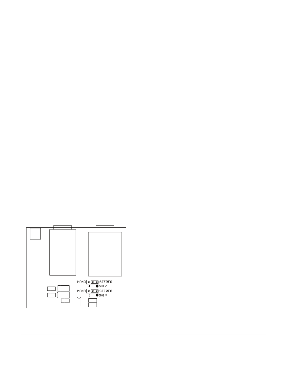
When using balanced mono sources, internal jumpers must
be moved as in the diagram below. Jumpers are wired at the
factory for stereo. Jumpers must be moved for balanced mono
operation. Each jack is jumpered separate, so any combination of
input types is possible within a single HC 6.
Any Channel not directly driven is automatically driven from
the MASTER INPUTS.
©Rane Corporation 080 7th Ave. W., Mukilteo WA 9875-5098 USA TEL 5-55-6000 FAX 5-7-7757 WEB www.rane.com
SIGNAL-PRESENT LEDS
These light up with any signal input above -20 dBu. They
are located in the signal path after the MASTER INPUTS and
before the individual LEVEL controls. This means that adjusting
the MASTER LEVEL affects the SIG LEDs, while adjusting the
individual LEVEL controls does not. When using a direct stereo
IN, the LED responds to that Input only. This means these
indicators aid in quickly identifying which stages are driven by
the MASTER INPUTS and which by the direct stereo INs:
Simply turn the MASTER LEVEL up and down and observe
which LEDs respond. These are the Channels being driven by
the MASTER INPUTS.
STEREO/MONO SWITCH
This serves the basic function of allowing both Left and
Right channels of all headphones to be driven from a mono
MASTER INPUT. In some instances a stereo program can be
confusing for live monitoring purposes, due to extreme separa-
tion and the increased difficulty in perceiving several different
volume levels. Using the MONO / STEREO switch converts the
system to mono operation to better suit these particular monitor-
ing needs.
FRONT PANEL OUTPUT JACKS
These jacks parallel the rear OUTs, providing easy access
patching into any Channel for cueing or additional monitoring.
When using more than six sets of headphones at once, keep two
things in mind:
1. There are still only six LEVEL controls. Additional headsets
must double up with those already in use. To avoid intolerable
volume differences to two listeners on the same channel of the
HC 6, use headphones of the same make and model.
2. The HC 6 has limited power output. The more headphones
you connect to it, the less power there is available to each set,
and the more strain on the HC 6. Blasting 10 or 12 sets of low
impedance headphones is asking too much from the HC 6. To
lessen the power drain from the HC 6, use only high imped-
ance (100 Ω or greater) headphones when paralleling.
PHONES
STEREO
INPUT
Figure . Moving internal jumpers near each Input jack convert stereo
unbalanced inputs to mono balanced inputs.