Front panel description, Dc 22 – Rane DC 22 (2003 version) User Manual
Page 4
Manual-
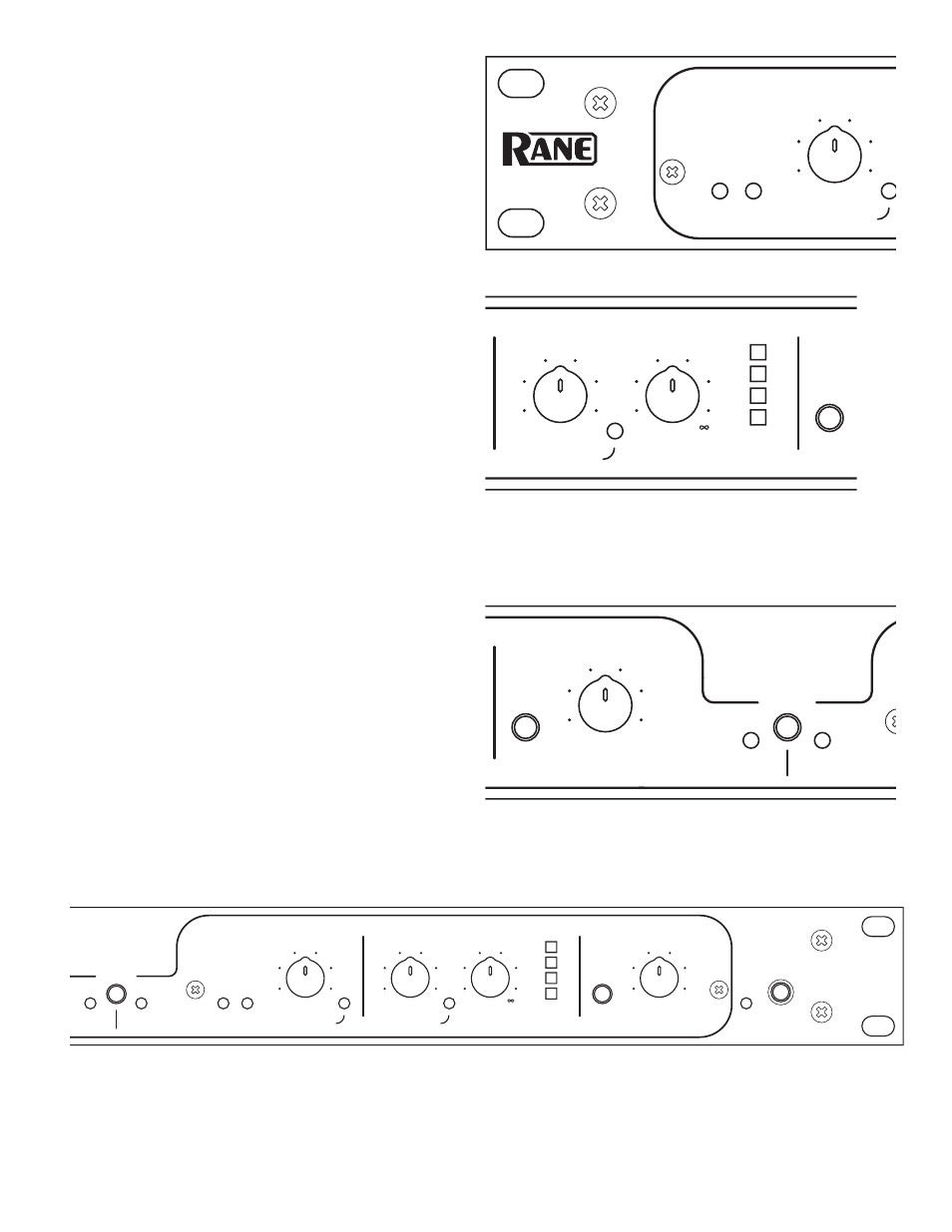
INPUT LEVEL indicators:
With signal applied, the +4 dBu
LED may light occasionally. If the OL (overload) LED flashes,
turn the output level down on the previous device.
GATE THRESHOLD control
sets the point at which the Input
signal level causes the Gate to become active.
_____________________________________________
COMPRESSOR THRESHOLD control
sets the point at
which the Input signal level causes the Compressor to become
active. See Figure 1 on page Manual-4.
COMPRESSOR RATIO control:
Once the Threshold is
exceeded, the Ratio of input change to output change is deter-
mined by this control. The compressor has no effect when set
at 1:1. But at 10:1, it takes a 10 dB input signal increase above
the Threshold to produce a 1 dB increase in Output Gain. See
Figure 2 on page Manual-4.
GAIN REDUCTION LEDs
show the amount of average signal
reduction in dB. This aids in setting the THRESHOLD and
RATIO controls by showing how much compression is occur-
ing.
_____________________________________________
BYPASS switch
compares the compressed and non-compressed
signal. There is one for each channel. The INPUT LEVEL
indicators remain active regardless of switch position.
OUTPUT LEVEL control
increases or decreases the output
gain of each Channel by 15 dB. In the center detent, gain will
be unity.
LINK switch
activates both Compressors when either channel’s
signal exceeds the set Threshold, preserving stereo imaging.
Switch this ON when using stereo material. The channel 1
controls become the Master when this switch is active, render-
ing the channel 2 controls and indicators dead.
_____________________________________________
Channel 2 controls
duplicate the controls in channel 1. These
are not active if the LINK switch is engaged.
Front Panel Description
SLAVE
THRESHOLD
OL
+4 dBu
MASTER
REDUCTION
GAIN
THRESHOLD
RATIO
BYPASS
LEVEL
GATE
INPUT
COMPRESSOR
LINK
OUTPUT
LEVEL
6
24
12
3
1
THRESHOLD
OL
+4 dBu
REDUCTION
GAIN
THRESHOLD
RATIO
BYPASS
LEVEL
GATE
INPUT
COMPRESSOR
OUTPUT
LEVEL
POWER
6
24
12
3
2
DC 22
dBu
dBu
:1
dB
-20
-60
-80
-70
-50
-40
-30
0
10
20
-40
-30
-10
-20
3
1.7
∞
∞
1
1.2
10
2
6
-6
12
15
-15
-12
0
dBu
dBu
:1
dB
-20
-60
-80
-70
-50
-40
-30
0
10
20
-40
-30
-10
-20
3
1.7
1
1.2
10
2
6
-6
12
15
-15
-12
0
DYNAMIC
CONTROLLER
Power switch
is your basic, straightforward power switch. When
the switch is depressed and the yellow LED is lit, the DC 22
is ready to go.