Manual-6 – Rane AC 24 User Manual
Page 8
Manual-6
5. Set the Delays starting with the driver furthest back (the one
that gets zero delay) and work outward (see Figure 4).
6. Hi-Mid / High Delay alignment:
a. Place the RTA mic in Position 1 as shown in Figure 4.
b. Set reference level for AC 24 High Output:
i) UnMUTE the High Output.
ii) Adjust the High Output LEVEL control so that an
adequate pink noise level is present.
iii) Adjust the High Output LEVEL so the RTA LED,
at the Hi-Mid / High crossover frequency, is green.
iv) MUTE the High Output.
c. Set reference level for AC 24 Hi-Mid Output:
i) UnMUTE the Hi-Mid Output.
ii) Adjust the Hi-Mid Output LEVEL so the RTA LED,
at the Hi-Mid / High crossover frequency, is green.
d. Set the High Output DELAY:
i) Referring to Figure 4, note the Hi-Mid Output is the
furthest back and requires no delay.
ii) UnMUTE the Hi-Mid and High Outputs.
iii) If the level goes down, driver polarity may be wrong.
Check the driver polarity before proceeding.
iv) Adjust the High Output DELAY for maximum
signal level in the RTA band associated with the
Hi-Mid / High crossover frequency.
7. Mid / Hi-Mid Delay alignment:
a. Place the RTA mic in Position 2 as shown in Figure 4.
b. Set the reference level for Hi-Mid Output:
i) UnMUTE the Hi-Mid Output.
ii) Adjust the Hi-Mid Output LEVEL so the RTA LED,
associated with the Mid / Hi-Mid crossover frequency,
is green.
iii) MUTE the Hi-Mid Output.
c. Set the reference level for the Mid Output:
i) UnMUTE the Mid Output.
ii) Adjust AC 24 Mid Output Level so the RTA LED,
associated with the Mid / Hi-Mid crossover frequency,
is green.
d. Set Mid Output Delay:
i) Referring to Figure 4, note that the Hi-Mid Output
is the furthest back and requires no delay.
ii) UnMUTE the Mid and Hi-Mid Outputs.
iii) If the level goes down, driver polarity may be
wrong. Check the driver polarity before proceeding.
iv) Adjust the Mid Output Delay for maximum signal
level in the RTA band associated with the Mid / Hi-Mid
crossover frequency.
8. Low / Mid Delay alignment:
a. Place the RTA mic in Position 3 as shown in Figure 4.
b. Set the reference level for the Mid Output:
i) UnMUTE the Mid Output.
ii) Adjust the Mid Output LEVEL so the RTA LED
associated with the Low / Mid crossover frequency is
green.
iii) MUTE the Mid Output.
iii) Record the Low / Mid crossover frequency.
iv) MUTE the AC 24 Low Output.
d. Unmute AC 24 Hi-Mid output.
i) The 1
st
low-side –6 dB red LED on the RTA
indicates the Mid / Hi-Mid crossover frequency.
ii) Adjust the MID / HI-MID Frequency to just light
the 1
st
low-side –6 dB red LED closest to the desired
crossover frequency.
iii) Record the Mid / Hi-Mid crossover frequency.
iv) The 1
st
high-side –6 dB red LED on the RTA
indicates the Hi-Mid / High crossover frequency.
v) Adjust the HI-MID / HIGH Frequency to just
light the 1
st
high-side red LED closest to the desired
crossover frequency.
vii) Note the Hi-Mid / High crossover frequency.
e. MUTE all AC 24 Outputs.
f. Set All AC 24 Output LEVEL controls to minimum.
4. Connect the Crossover to the Amplifiers:
a. Amplifiers off.
b. Connect Crossover Outputs to appropriate amplifiers.
c. If you have gain controls on your amps, set these for the
desired sensitivity (input voltage required to clip the amp).
1
d. Do not adjust amplifier sensitivity controls after you have
set crossover Output Levels.
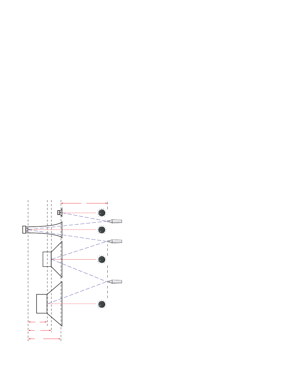
e. Place the RTA microphone about 24 inches [60 cm] away
from the speaker stack, as close to equidistant to each driver
as possible (see Figure 4).
f. Set the RTA scale to 1 dB if available.
i. Turn on the RTA Pink Noise.
j. Turn on the amplifiers.
9"
11"
15.5"
24"
POSITION 1
HI-MID = 0 ms DELAY
HIGH = 1.14 ms DELAY
MID = 0.81 ms DELAY
LOW = 0.663 ms DELAY
POSITION 2
POSITION 3
(61 cm)
(22.9 cm)
(27.94 cm)
(39.4 cm)
0
10 ms
0
10 ms
0
10 ms
0
10 ms
mic
mic
mic
Figure 4. Delay setttings calculated using furthest driver as zero.