Manual-8, Fix-lt-with-the-crossover school – Rane AC 24 User Manual
Page 10
Manual-8
6. Realtime Analyzer setup:
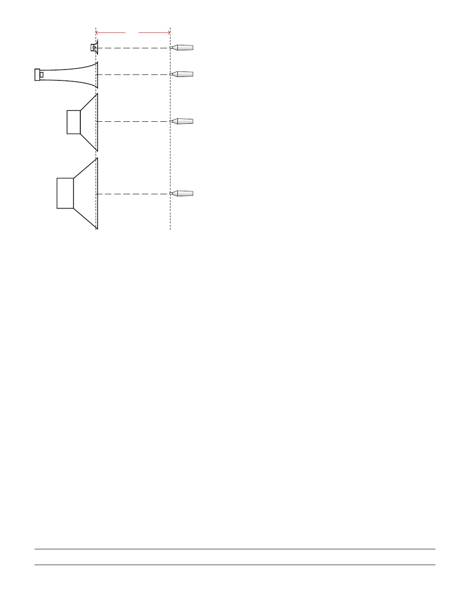
a. Place the RTA mic on axis, 1 meter away from
the Low driver as shown in Figure 5, Position 1.
b. Set the RTA SPL Filter to C-Weighting.
c. Turn on the Pink Noise.
7. Make sure the Pink Noise Level coming into the crossover is
able to light the red OL indicator.
8. Set SPL
MAX
for each driver (one Output at a time):
a. Depending on the maximum safe SPL rating of your
system, you may want to use ear protection.
b. Place the RTA mic on axis at 1 meter (see Figure 5).
c. UnMUTE the AC 24 Output associated with the driver
you are setting the Limiter for.
d. Slowly increase the LIMIT Threshold until the RTA SPL
meter reads the SPL
MAX
calculated in step 4 for the driver
you are setting the Limiter for.
e. MUTE the associated AC 24 Output.
f. Repeat for each driver.
Method Two: Voltage at the driver.
Method Two uses the voltage at the driver instead of the SPL.
Using voltage is not as desirable as SPL because impedance often
varies with frequencies. Manufacturers provide the maximum
recommended continuous power (P) and Nominal Impedance
(R) ratings for each Driver. The maximum voltage is calculated as
follows:
• V
MAX
= √(P*R)
P = Maximum Power
R = Nominal Impedance
• Calculate V
MAX
for each driver.
• Follow the steps outlined above for setting Limiters using SPL.
Simply substitute volt meter readings for RTA SPL readings.
System calibration is complete!
We highly recommend installing the included security
cover As Soon As Possible!
Fix-lt-With-The-Crossover School
Consider the following (now that you have worked so hard to
accurately set up the crossover). Some maintain that a good active
crossover can work alone like a parametric equalizer in the hands
of an expert. This does require experience, skill, and the right
equipment to back it up (not to mention a licensed set of ears).
Regardless of which school you profess, the absolute importance
and effectiveness of some kind of realtime analyzer in your system
cannot be overstressed! Analyzers in general have come a long
way. An analyzer saves tremendous amounts of time and provide
the absolute consistency, accuracy, and plain old good sound that
few ears on this earth can deliver. You’ll wonder how you man-
aged without one.
39.4"
POSITION 4
POSITION 1
POSITION 2
POSITION 3
(1 meter)
mic
mic
mic
mic
Figure 5. Setting Output Levels with a calibrated mic.
STEP FIVE: Setting Limiters
Each AC 24 Crossover Output has a Limiter. Each Limiter has an
independent Threshold control with a range of 0 dB FS to –64
dB FS. To maintain spectral accuracy, Mid, Hi-Mid and High
Limiters are linked. Linking is accomplished with wired-or con-
trol. These outputs all receive the same gain reduction regardless
of which one initiates limiting. Independent Threshold indicators
show which band is the source of the limit condition. The Low
Output Limiter may operate independently. This is often desir-
able to prevent “pumping” or modulating higher frequencies. If
desired, there is a Low Limit Link switch.
Method One: Driver SPL.
1. Do not change any of the previously calibrated AC 24 Output
Level controls.
2. Do not change any amplifier gain controls.
3. MUTE all AC 24 Outputs.
4. Set all LIMIT controls to –64.
5. Determine the maximum SPL for each driver.
a. Find the manufacturers sensitivity rating
(dB SPL @ 1 watt, @ 1 meter ) = dB SPL
REF
b. Find the manufacturers maximum continuous power
rating (P
MAX
)
c. SPL
MAX
= dB SPL
REF
+ [10*Log(P
MAX
)]
106220
©Rane Corporation 10802 47th Ave. W., Mukilteo WA 98275-5098 USA TEL 425-355-6000 FAX 425-347-7757 WEB www.rane.com