Manual-2 – Rane AC 24 User Manual
Page 4
Manual-2
100
31.5
80
40
63
50
315
125
200
250
160
500
160
400
200
315
250
1.6k
630
1.0k
1.25k
800
4.0
1.25
3.15
1.6
2.5
2.0
12.5
5.0
8.0
10.0
6.3
4
2
8
4
2
8
100
31.5
80
40
63
50
315
125
200
250
160
500
160
400
200
315
250
1.6k
630
1.0k
1.25k
800
4.0
1.25
3.15
1.6
2.5
2.0
12.5
5.0
8.0
10.0
6.3
4
2
8
4
2
8
Hz
-64
0
4-WAY
4-WAY
4-WAY
kHz
kHz
4-WAY
4-WAY
Hz
kHz
4-WAY
kHz
kHz
4-WAY
CROSSOVER
kHz
Hz
Hz
0
10
0
10
0
10 ms
-64
0
0
10 ms
-64
0
0
10 ms
-64
0
0
10 ms
-64
0
0
10 ms
-64
0
0
10 ms
-64
0
0
10 ms
0
10
0
10
0
10
-64
0
0
10 ms
0
10
0
10
0
10
0
10
0
10
AC 24
MID
CHANNEL
B
CHANNEL
A
LOW
FREQ
FREQ
FREQ
FREQ
HI-MID
HIGH
LEVEL
LEVEL
INPUT
LIMIT
OL
MONO LOW
STEREO LINK
LINK
LINK
DELAY
LIMIT
DELAY
LIMIT
DELAY
LIMIT
DELAY
LIMIT
DELAY
LIMIT
DELAY
LIMIT
DELAY
LIMIT
DELAY
MUTE
LEVEL
LEVEL
MUTE
MUTE
MUTE
LEVEL
MUTE
HI-MID
HIGH
HORN EQ
FREQ
HI-MID
HIGH
HORN EQ
POWER
MID
LOW
FREQ
FREQ
FREQ
HI-MID
HIGH
LEVEL
LEVEL
INPUT
OL
MUTE
LEVEL
LEVEL
MUTE
LEVEL
MUTE
M
A
S
T
E
R
S
L
A
V
E
1
9
9
3
4
3
4
3
4
3
5
6
8
9
9
7
7
7
7
2
2
2
2
11 10 1
9
9
3
4
3
4
3
4
3
5
6
8
9
9
7
7
7
7
2
2
2
2
12
FREQ
FREQ
FREQ
LEVEL
MONO LOW
STEREO LINK
LIMIT
LINK
LIMIT
LIMIT
LIMIT
DELAY
DELAY
DELAY
DELAY
MUTE
MUTE
MUTE
LEVEL
LEVEL
LEVEL
LEVEL
MUTE
HI-MID
HIGH
FREQ
FREQ
FREQ
LEVEL
POWER
LIMIT
LINK
LIMIT
LIMIT
LIMIT
DELAY
DELAY
DELAY
DELAY
MUTE
MUTE
MUTE
LEVEL
LEVEL
LEVEL
LEVEL
MUTE
HI-MID
HIGH
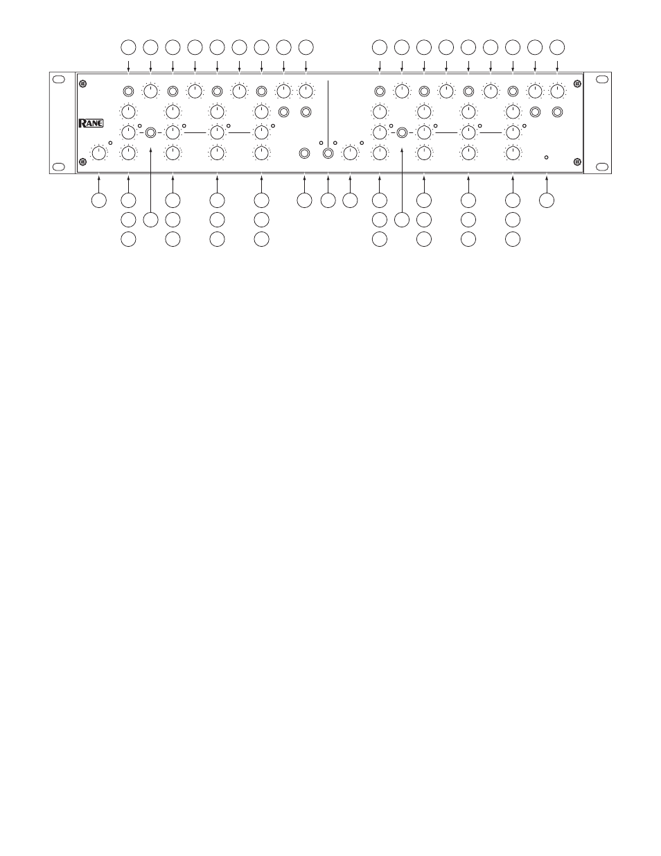
1
Channel INPUT LEVEL controls and OL indicator:
Set the overall Levels of Channels A and B without altering the relative
settings of the Low, Mid, Hi-Mid and High frequency Outputs. The range is 80 dB, and maximum gain is 6 dB. The OL warn-
ing indicator lights 4 dB before clipping. Audio taper is down 16 dB at the center of rotation (dot 5). Unity gain is the white dot
between dots 7 and 8.
2
Low, Mid, Hi-Mid and High Output LEVEL controls:
Sets the signal Level going to each of the Crossover Outputs. The Hi-Mid
control is inactive in 3-Way Mode. Refer to ‘Setting the Output Level Controls’ on page Manual-7. Audio taper is down 16 dB at
the center of rotation (dot 5). Unity gain is the white dot between dots 7 and 8.
3
Low, Mid, Hi-Mid and High Output MUTE switches:
When pressed to the in position, all signal is removed from the respective
frequency Output. This eases tune-up procedures as described beginning on page Manual-4.
4
Crossover FREQUENCY controls
: Set the crossover frequencies between the Low, Mid, Hi-Mid and High frequency Outputs.
The Hi-Mid control is inactive in 3-Way Mode. Refer to ‘Select Crossover Frequencies’ on page Manual-4.
5
Hi-Mid Output CD HORN EQ and engage switches:
When the switch is pressed to the in position, the CD Horn EQ is active
when the AC 24 is in 4-Way mode. If CD Horn EQ is not required, make sure the HORN EQ filters are off and frequency settings
are at 8 kHz. Refer to ‘Set CD Horn EQs’ on page Manual-7.
6
High Output CD HORN EQ and engage switches:
When the switch is pressed to the in position, the CD Horn EQ is active. If
CD Horn EQ is not required, make sure the HORN EQ filters are off and frequency settings are at 8 kHz.
7
Output LIMIT controls and indicators:
These are Thresholds for each of the Output Limiters, with a range of 0 to -64 dBFS. To
maintain spectral accuracy, Mid, Hi-Mid and High frequency Outputs are linked, so that any signal that crosses a Threshold will
limit all three Outputs equally (see 8). The independent Threshold indicators show which band is the source of the limit condition.
Refer to ‘Setting Limiters’ on page Manual-8.
8
Low Output LIMITER LINK switch:
The Limiter for the Low Output is independent of the Mid, Hi-Mid and High frequency
Output Limiters. This is often desirable to prevent “pumping” or modulating higher frequencies. Depressing this switch “links” the
Low Limiter to the other limiters. Refer to ‘Set Limiters’ on page Manual-8.
9
Low, Mid, Hi-Mid and High Output DELAY controls
: Add from 0 to 10 ms of signal Delay to each of the Crossover Outputs
(10 ms = 135 inches = 11.313 feet = 3.429 meters). This allows a driver to be electronically phase-aligned with a driver whose dia-
phragm is situated behind the other. Refer to ‘Adjust Signal Delay’ on page Manual-5.
0
STEREO LINK switch:
This switch links CHANNEL A as the MASTER to CHANNEL B as the SLAVE, useful in stereo ap-
plications. In this mode, the MASTER (A) controls all of the SLAVE’s (B) DSP functions, leaving Channel B’s controls inactive.
When using the Stereo Link, we recommend setting the SLAVE (B) Outputs to minimum. This prevents unwelcome surprises if the
STEREO LINK switch is turned off.
q
MONO LOW Output switch:
Sums the Outputs of Channels A and B, appearing at the Channel A LOW Output.
w
POWER indicator:
When this yellow LED is lit, you guessed right — the unit is on and ready.