Operation – Ryobi RT102 User Manual
Page 15
15
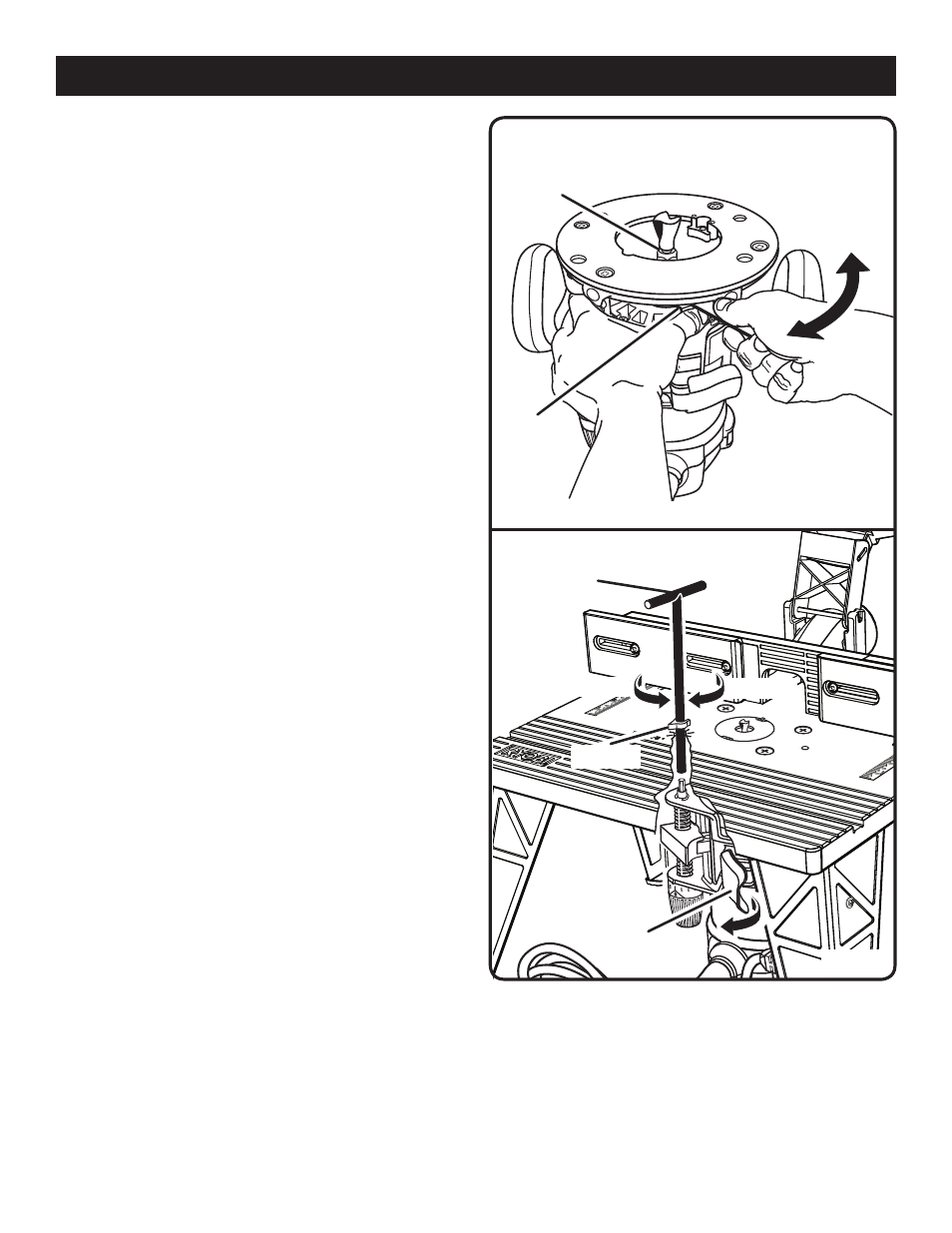
To
LooSEN
SPINDLE
LoCK
To
TIGHTEN
CoLLET
NUT
Fig. 17
INSertING/reMOVING CUtterS
See Figure 17.
Unplug the router table.
Remove the screws from the router guard.
Remove the router guard from the router.
to install the bit:
Push the spindle lock in and hold into place.
NOte: To make sure the spindle is locked, depress the
spindle lock and turn slowly until the spindle locks into
place and stops turning.
Loosen the collet nut and remove the bit.
Insert the bit until it is approximately 1/8 in. to 1/4 in. away
from the collet nut face.
NOte: Make sure that the collet always clamps the shank
(non-cutting end) of the bit.
Tighten the collet nut securely by turning it clockwise with
the wrench provided.
Release the spindle lock.
to remove the bit:
Push the spindle lock in holding it into place.
Loosen the collet nut and remove the bit.
Release the spindle lock.
Return the router guard to its proper position.
Secure the router guard by inserting and tightening the
two screws previously removed.
aDJUStING DeptH OF CUt
See Figure 18.
We recommend that cuts be made at a depth not exceeding
1/8 in. (3 mm) and that several passes be made to reach
depths of cut greater than 1/8 in. (3 mm).
Unplug the router table.
Unlock the locking clamp.
Insert the T-handle wrench into the hole in the router
table.
Align the T-handle wrench pointer with the desired tick
mark on the table.
Turn wrench until router bit reaches the desired depth of
cut. Each tick mark equals 1/64 in.
Lock the locking clamp securely after desired depth of
cut is reached.
NOte: When you use certain cutters, you may need
to remove the clear plastic subbase from the router to
achieve full depth of cut.
T-HANDLE WRENCH
LoWER BIT
RAISE BIT
LoCKING
CLAMP
PoINTER
Fig. 18
OperatION
RoUTER SHoWN WITHoUT TABLE FoR CLARITY