Assembly – Ryobi RT102 User Manual
Page 11
11
MITER GAUGE
SLoT
BAR
aSSeMBLY
Fig. 6
attaCHING tHe UNDer taBLe GUarD
See Figure 5.
Place the router table upside down on a flat surface.
Position the under table guard around the throat of the
table.
Align the three holes of the guard with the threaded holes
in the table.
Use the hex key to secure the under table guard with
three socket head screws and three 6 mm flat washers.
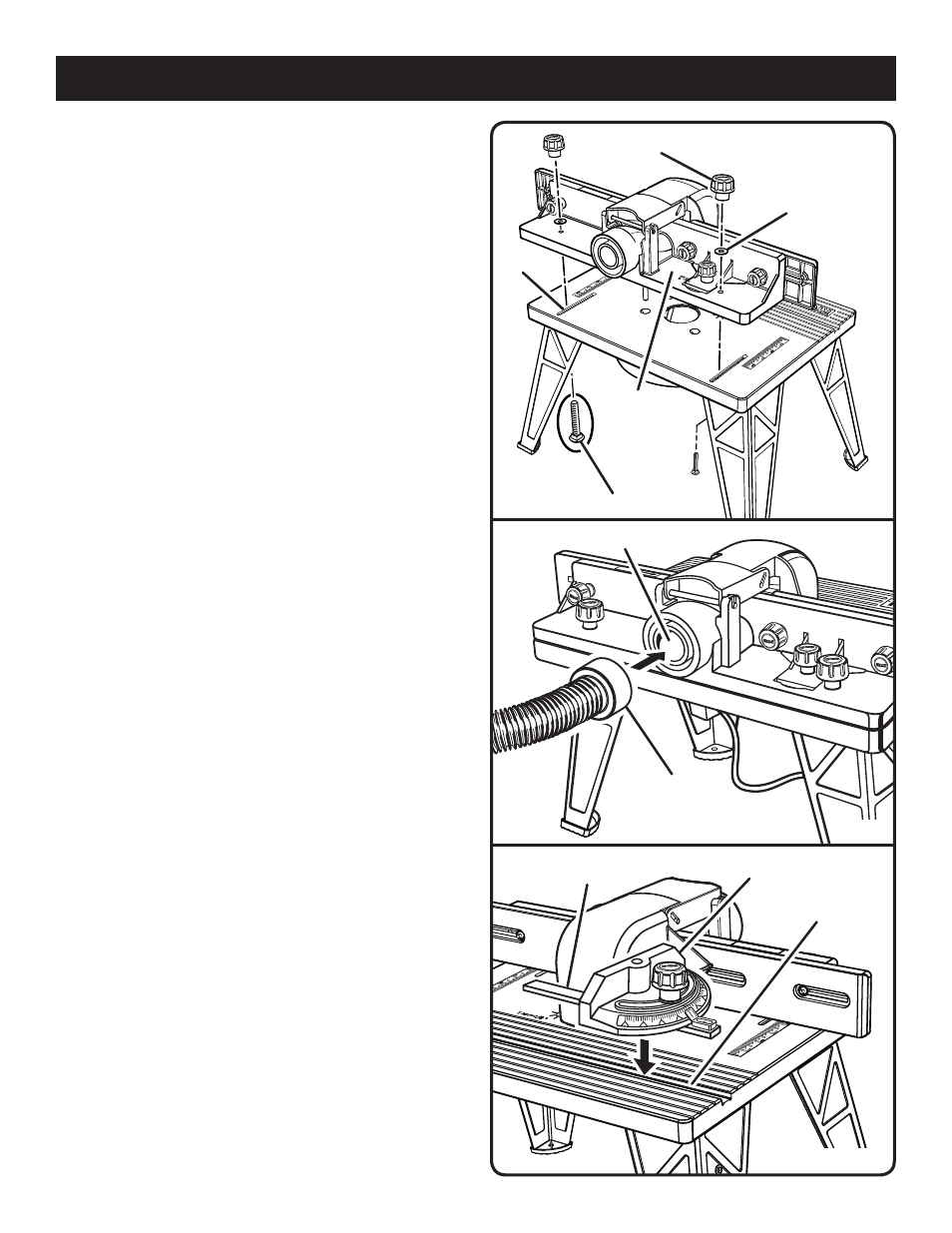
attaCHING tHe FeNCe aSSeMBLY
See Figure 6.
Place the router table right side up with the back edge
closest to you.
Insert the carriage bolts through the slot in the router
table and through the holes in the fence assembly.
Slide the fence lock knob washer over the carriage
bolts.
Install the fence lock knobs over the carriage bolts.
Tighten the fence lock knobs.
attaCHING tHe VaCUUM HOSe
See Figure 7.
The dust ports molded into the fence will accept either a
1-1/4 in. or -1/ in. vacuum attachment.
INStaLLING tHe MIter GaUGe
See Figure 8.
With the router table right side up, and the front edge closest
to you, place the miter gauge bar in the slot near the front
of the table with the pointer on the right.
FENCE LoCK KNoBS
CARRIAGE BoLTS
FENCE LoCK
KNoB WASHER
FENCE
ASSEMBLY
VACUUM HoSE
DUST EXHAUST
Fig. 7
SLoT
Fig. 8