Installation instructions, Install brackets, Mark the holes – Outdoor Great Room Cordless Sun Shade User Manual
Page 2: Install the shade, Alternativa de arreglo de polea
Your shade comes standard with the clutch on the right side of the shade (Fig. 1) and ready to
be mounted on the inside or outside of your window frame. If you purchased a custom shade,
or intend to keep your shade with the standard settings, you may skip this section and proceed
to the installation instructions.
If you want to move the clutch to the left side of the shade or you want to hang your shade from
the top of the window (or ceiling), you will need to make a few simple changes to your shade
before proceeding to the installation instructions. Refer to the Alternate Clutch Setup
section of the manual for instructions on how to make these changes.
Refer to the front page of this manual for help identifying the various components of the shade.
imPortant: The screws included in your hardware kit are for use with wood only. See your
dealer for mounting recommendations when attaching your shade to any other material.
installation instructions
Idle UnIt bracket
clUtch UnIt bracket
Snap end plUg
Into end UnIt
2. install Brackets
Install the Clutch and Idle End Brackets
(Fig 3). The Clutch Unit Bracket will be
on the right side, and the Idle End Unit
Bracket should be on the left for
standard installation.
do not tighten screws completely yet.
1. mark the holes
• For stock shades, use (Fig 2) to determine the
placement of your screws.
• For custom shades, mark holes 1/2” less than
overall (bracket-to-bracket) measurement at
each end.
3. install the shade.
First, insert the Clutch Plug into the Clutch
Unit (Fig. 4).
Then insert the Idle End Plug into the
Idle End Unit, and snap the Idle End Plug
securely into place (Fig. 5).
With the shade in place, adjust the brackets
so they fit snugly on each end of the shade.
imPortant:
now go back and tighten the Bracket
screws completely.
Fig. 3
Fig. 2 (the above measurements are for stock shades)
clUtch end plUg
Fig. 4
Fig. 5
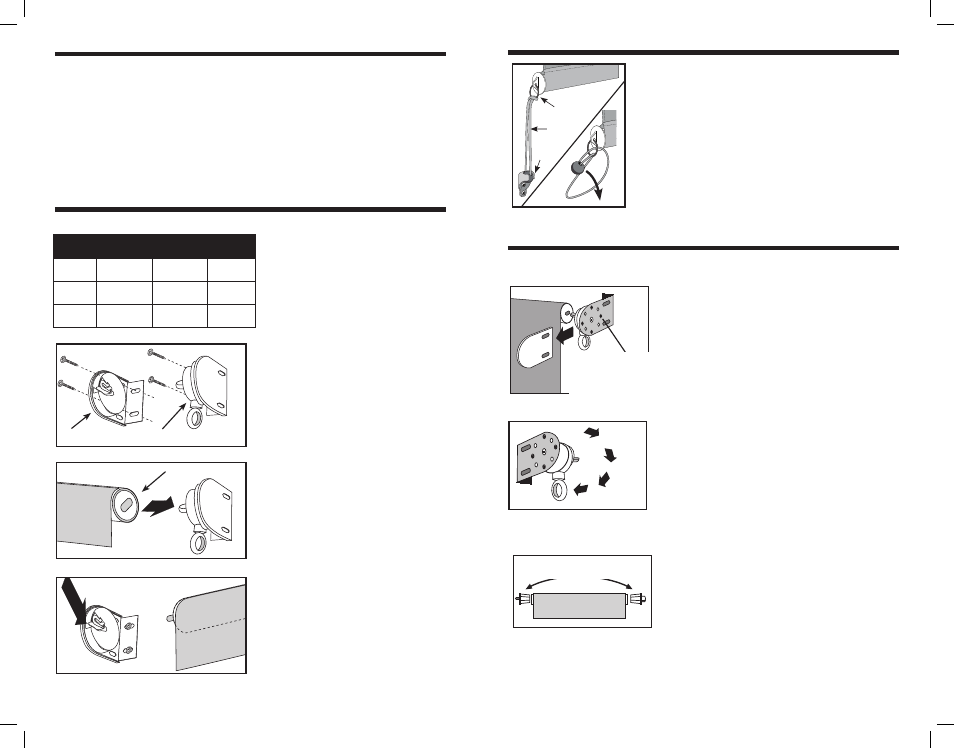
5. Instale anclajes (Si desea)
Anclajes ha sido proporcionado para asegurar su persiana
solar en condiciones de viento.
nota: Las persianas deben de ser enrolladas en
temporada de viento o cuando hay exposición prolongada
para prevenir daños.
Fig 6
1. Enrosque el elástico a través del anillo de la tapa de
extremo y vuelva a enroscar a través del mismo haciendo un
nudo de la cabeza de Lark (figura 6).
2. Instale el receptor a una distancia de aproximadamente
12,70 cm debajo de la parte inferior de donde la persiana se
detendrá, para permitir una tensión adecuada de la cuerda
elástica.
Se han proporcionado tornillos de madera. Si instala en otro material
diferente a la madera, puede necesitar tornillos adicionales.
elástico
Anillo de tapa
de extremo
receptor
cloth
Width
screW-to-screW
measurement
oVerall Width
(Bracket-to-
Bracket)
aPProximate
WeiGht
72 in.
(1.83 m)
73.25 in.
(1.86 m)
74.75 in.
(1.9 m)
7 lb.
(3 kg)
96 in.
(2.44 m)
97.25 in.
(2.47 m)
98.75 in.
(2.51 m)
9 lb.
(4 kg)
120 in.
(3.05 m)
121.25 in.
(3.08 m)
122.75 in.
(3.12 m)
11 lb.
(5 kg)
alternatiVa de arreGlo de Polea
Su persiana requerirá una instalación que no es estándar si:
1) Usted quiere cambiar el mecanismo de polea al lado izqui-
erdo de la persiana, o 2) Usted quiere montar la persiana en
el techo.
nota: Si usted compro una persiana especial o esta
instalando una persiana uniforme, no necesita hacer estos
cambios.
camBiando el mecanismo de
Polea a un control izQuierdo
Si usted quiere que su mecanismo de polea este en el lado
izquierdo de la persiana, usted necesita hacer un cambio
sencillo a su soporte de polea antes de instalar la persiana.
Para hacer este cambio, comience deslizando las tapas de
soporte en el soporte de polea y el soporte parado (Fig. 7).
Quite los cuatro tornillos de los dos soportes.
Gire el soporte de polea 180 grados para que el mecanismo
de polea pueda colgar hacia abajo (Fig. 8). Vuelva a poner
los tornillos y deslice la tapa de soporte. Ningún cambio es
necesario en el soporte parado. Remueva los dos tapones
en el tubo y cámbielos. (Fig. 9)
retIre LoS (4) tornILLoS
PArA CAmBIAr eL
ControL deL LAdo
dereCho AL LAdo
IzquIerdo.
Fig. 7
GIre LA
PoLeA 180º
Fig. 8
CAmBIe LoS (2) tAPoneS
termInALeS
Fig. 9