Connecting units to form combinations, Mounting modular brake units (mbu) – Nexen MBU-875 930200 User Manual
Page 7
7
FORM NO. L-20134-J-1211
NOTE
Make sure the air inlet ports are properly aligned for
your mounting requirements.
5. Using the four Socket Head Cap Screws (Item 31), secure
the MBU to the MDU (See Figure 4).
CONNECTING UNITS TO FORM COMBINATIONS
(continued...)
6. Alternately and evenly tighten the four Socket Head Cap
Screws (Item 31) to 35 ft-lb [47 Nm] torque (See Figure 4).
7. Place the Key (Item 19) into the shaft of the Modular Input
Unit (MIU). Slide the MIU shaft into MDU (See Figure 4).
8. Using the four Hex. Head Jam Nuts (Item 45), Hex. Head
Cap Screws (Item 33), and Lock Washers (Item 24), secure
the MIU to the MDU (See Figure 4).
9. Alternately and evenly tighten the four Hex. Head Jam Nuts
(Item 45) to 20 ft-lb [27 Nm] torque (See Figure 4).
MODULAR INPUT BRAKE (MIB)
Models 625 and 875
1. Remove the six Machine Screws (Item 25) that secure the
Friction Facing (Item 9) to the MBU Disc Journal (Item 8)
and save the Machine Screws and Friction Facing as spare
parts (See Figure 5).
2. Place the Key (Item 19) into the shaft of the Modular Input
Unit (MIU); then, slide the MIU shaft into the Modular Brake
Unit (MBU) (See Figure 5).
3. Using the four Hex. Head Jam Nuts (Item 45), Hex. Head
Cap Screws (Item 33), and Lock Washers (Item 24), secure
the MIU to the MBU (See Figure 5).
4. Alternately and evenly tighten the four Hex. Head Jam Nuts
(Item 45) to 20 ft-lb [27 Nm] torque (See Figure 5).
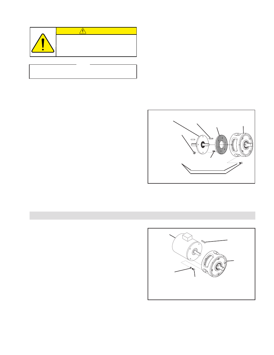
MODELS 625 AND 875 TO A MOTOR
1. Remove the six Machine Screws (Item 25) that secure the
Friction Facing (Item 9) to the MBU Disc Journal (Item
8) and save the Machine Screws and Friction Facing as
spare parts (See Figure 5).
2. Place the Key (Item 19) into the motor shaft; then, slide
the motor shaft into the Modular Unit (See Figure 6).
3. Rotate the Modular Unit until the clearance holes in the
Modular Unit are aligned with the tapped holes in the
Motor; then, using the four Hex. Head Cap Screws (Item
33) and Lock Washers (Item 24), secure the motor to the
Modular Unit (See Figure 6).
4. Alternately and evenly tighten the four Hex. Head Cap
Screws to 20 ft-lb [27 Nm] torque.
MOUNTING MODULAR BRAKE UNITS (MBU)
(continued...)
FIGURE 5
Modular
Input Unit
Hex. Head Jam
Nut (Item 45)
Hex. Head
Cap Screws
(Item 33) and
Lock Washers
(Item 24)
Key
(Item 19)
Modular
Brake Unit
Friction
Facing
(Item 9)
Machine Screw
(Item 25)
Modular
Unit
Key
(Item 19)
Motor
Hex. Head
Cap Screw
(Item 33)
FIGURE 6
Lock
Washer
(Item 24)
CAUTION
Never substitute Hex. Head Cap
Screws for the Socket Head Cap
Screws (Item 31).