Parts replacement – Nexen MBU-875 930200 User Manual
Page 14
14
FORM NO. L-20134-J-1211
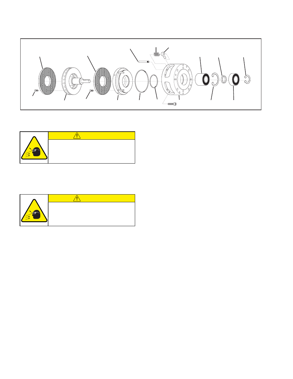
Refer to Figure 13.
1. Using a screw driver inserted through the holes in the back
side of Housing (Item 2), remove the four Spring Guide Pins
(Item 17); then, remove the Compression Springs (Item 15)
and Eye Pins (Item 18) through the openings in the Housing
(Item 2).
2. Remove the Retaining Ring (Item 38).
3. Fully support the Housing (Item 2) and press the Disc Journal
(Item 8) out of the Housing.
4. Using a bearing puller, remove the old Ball Bearing (Item
28) from the Housing (Item 2).
5. Remove the Spacer (Item 12) and Retaining Ring (Item 39)
from the Housing (Item 2).
6. Press the old Ball Bearing (Item 29) out of the Housing (Item
2).
7. Slide the Piston (Item 5) out of the Housing (Item 2) .
8. Remove old O-Ring Seals (Items 42 & 44) from Piston (Item
5).
9. Remove the six old Flat Head Screws (Item 25) securing
the old Friction Facing (Item 9) to the Piston (Item 5) and
remove the old Friction Facing.
10. Using six new Flat Head Screws (Item 25), secure a new
Friction Facing (Item 9) to the Piston (Item 5) .
11. Tighten the six flat Head Screws to 22 in-lb [2.50 Nm]
torque.
12. Remove the six old Flat Head Screws (Item 25) securing
the old Friction Facing (Item 9) to the Disc Journal (Item 8)
and remove the old Friction Facing.
13. Using six new Flat Head Screws (Item 25), secure a new
Friction Facing (Item 9) to the Disc Journal (Item 8).
14. Tighten the six flat Head Screws to 22 in-lb [2.50 Nm]
torque.
15. Clean the Bearing Bore of Housing (Item 2) with fresh
solvent, making sure all old Loctite
®
residue is removed.
16. Apply an adequate amount of Loctite
®
680 to evenly coat
the outer race of the new Ball Bearing (Item 29) and press
the new Ball Bearing into the Housing (Item 2).
17. Reinstall Spacer (Item 12) and Retaining Ring (Item 39).
18. Apply an adequate amount of Loctite
®
680 to evenly coat
the outer race of the new Ball Bearing (Item 28) and press
the new Ball Bearing into the Housing (Item 2).
19. Lubricate the new O-Ring Seals (Items 42 and 44) and the
O-Ring contact surfaces of the Housing (Item 2) and Piston
(Item 5) with a thin film of fresh O-Ring lubricant.
20. Reinstall the new O-Ring Seals (Items 42 and 44) onto the
Piston (Item 5); then, align the pins on the Piston with the
holes in the Housing (Item 2) and slide the Piston into the
Housing.
21. Support the inner race of the new Ball Bearing (Item 28)
and press the Disc Journal (Item 8) into the Ball Bearings
(Items 28 and 29) and Housing (Item 2).
22. Reinstall the Retaining Ring (Item 38).
23. Install a Compression Spring (Item 15) on each Spring
Guide Pin; then, compress the Compression Springs and
insert the four Eye Pins (Item 18) into the four holes in the
Piston (Item 5), aligning the Compression Springs with the
holes in the Housing (Item 2).
24. Slide the Spring Guide Pins (Item 17) through the
Compression Springs (Item 15) and the holes in the Eye
Pins (Item 18), screwing each Spring Guide Pin into the
Housing.
PARTS REPLACEMENT
(continued...)
MODULAR BRAKE UNIT (MBU)
Models 625 and 875
25
42
17
15
18
28
39
2
44
8
5
9
9
29
12
38
25
FIGURE 13
CAUTION
Special attention should be exercised
when working with retaining rings. Always
wear safety goggles when working with
spring or tension loaded fasteners or
devices.
CAUTION
The four Guide Spring Guide Pins (Item
17) hold the four Compression Springs
(Item 15) in place. Always wear safety
goggles when working with spring or
tension loaded devices.