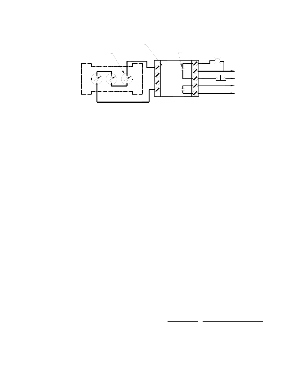
Figure 4: proper thermistor wiring – Metalfab Hindon-Invicta L Series User Manual
Page 8
6
4.0
OPERATION
4.1
Electrical
Prior to operation, ensure that the electrical voltage is correct and that feed cable(s) to the
vibrator(s) are correctly sized for the load and mechanical requirements. The method of starting
should be direct, on-line for all vibrator sizes. Unless using an inverter or soft start system, a
push button starter with thermal overloads is recommended.
4.2
Mechanical
Prior to operation, confirm that all mounting bolts are tight and properly torqued. It is
recommended that all mounting fasteners be checked and re-tightened within several hours after
initial operation to ensure a secure mounting.
4.3
Start-up
Upon completion of sections 4.1 and 4.2, the vibrator can now be started.
After initial start-up, verification of proper thermal overload (heater) selection should be
performed by measuring actual running current of the vibrator. Re-size heater elements if necessary
for proper protection. Periodically re-torque mounting bolts during routine maintenance periods.
In the event of any start-up problems, please refer to SECTION 6 - TROUBLESHOOTING.
1
2
3
C
4
5
6
7
8
INTERNAL CONTACT SHOWN IN
"TRIPPED" CONDITION
TO CONTROL CIRCUIT
RESET SWITCH
120 VAC INPUT
ONE (1) SENSOR PER PHASE
TERMINATED AT VIBRATOR
TERMINAL BOX
SENSOR INPUTS
VIBRATOR
CONTROL MODULE TO SENSOR
WIRING DIAGRAM
Figure 4: Proper Thermistor Wiring