Bradford White M-I-MH40T6FLX User Manual
Page 18
18
Gas Conversion Instructions continued-
c) If the gasket is not effected by any of the above, gasket replacement is not
required.
d) If gasket replacement is required, contact manufacturer for inner door gasket
replacement kit.
5) Disconnect thermocouple, gas supply tube, and pilot from gas valve and remove
burner assembly from water heater.
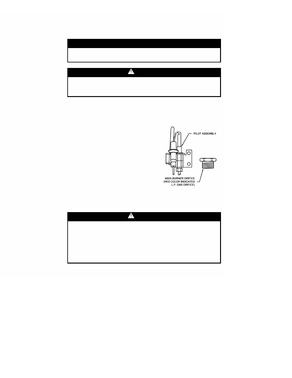
6) Remove “RED” color coded main burner orifice and pilot assembly and replace
with orifice and pilot assembly provided in cloth bag attached to the water heater.
7) Replace the burner assembly and reconnect all fittings and check for leaks.
8) Refer to “Gas Connections”.
9) Replace inner doors with the following
procedure.
a) Clean any residual gasket residue or other
debris from combustion chamber surface
before installing the inner door/gasket
assembly.
b) Place the left side inner door into position
first. Firmly position the radiused channel of the
inner door around the feedline. Using the 1/4”
hex drive screws from step 4, secure left side
inner door in place. DO NOT
OVER TIGHTEN SCREWS.
c) Position thermocouple, pilot tube and Piezo wire against left side inner door
flange gasket. DO NOT ROUTE THROUGH RADIUSED CHANNEL WITH
FEEDLINE.
IMPORTANT
If gasket replacement is required, contact the manufacturer for
inner door gasket replacement kit.
WARNING
If the information in these instructions is not followed exactly, a
fire or explosion may result causing property damage, personal
injury or death.
WARNING
Stripped fastener connections may allow for seal breach of inner
door. A seal breach may result in a fire or explosion causing
property damage, personal injury or death. Do not over tighten
screws.
If a fastener connection is stripped, contact the manufacturer
listed on the water heater rating plate.